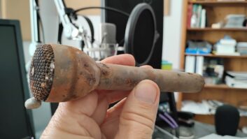
A corroded RF connector, sealed only with electric tape. Consultant Tom Osenkowsky recently received a call from a contract engineer. His client’s two-tower AM directional antenna produced erratic antenna monitor readings. The engineer wondered which phasor controls to adjust in order to bring the array back within licensed values.
Tom urged him to take a set of monitor point readings in the two deep nulls during both “good” and “bad” antenna monitor readings. The engineer did so, noting no change in the field.
This indicated to Tom that the problem was in the sampling system that was feeding the antenna monitor, not in the RF feeder system. His hunch was verified by examining the sample-loop connectors. Connector 1 was sealed using multiple layers of electrical tape. Connector 2 was sealed properly, using the manufacturer’s heat shrink weatherproofing kit.
The differences are obvious when you compare Fig. 1 and Fig. 2. Cutting corners and not using the coaxial cable manufacturer’s weatherproofing kit can cause the kind of damage seen in Fig. 1. Not only does the work need to be repaired, but this negates any money-saving rationale for the electrical tape process in the first place.
Thankfully for the station, the contract engineer sought advice before adjusting the phasor. By replacing both connectors and sealing them properly following the manufacturer’s instructions, the engineer returned the antenna monitor readings to normal.
Thanks, Tom, for a great troubleshooting tip.
***

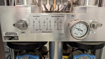
A manufacturer’s weatherproofing kit guards against corrosion.Another phasor adjustment tip: Check the couplings that connect the variable capacitors or inductors before making adjustments. Most phasor controls have “turns counters” that give you a reference of where the inductor or capacitor is set; and sometimes the set screws on these couplings get loose.
The result is a nightmare. As you adjust the components, the loose setscrews permit the variable component shafts to turn erratically. In a situation like this, the “turns counter” indications become worthless.
So what do you do? A common phasor maintenance procedure is to rock the controls while a second engineer observes that the coupling is not slipping as the adjustment knob is turned. (Of course, turn off all RF power to the phasor for the procedure.)
You should perform this procedure before making any major phasor adjustment. Tightening all hardware inside the phasor and antenna-coupling network also makes sense.
***

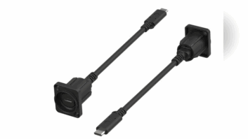
LED lighting sources illuminate dark spaces.Phillip Vaughan is chief engineer of Southern California’s K-FROG. In past issues, we’ve shared engineers’ ideas on how to illuminate dark locations using LED lighting. Phillip recently installed some new studio furniture, but due to the configuration he found very low visibility behind the equipment.
He decided to buy a 12-volt supply and some stick-on LED strips; he reports that it works beautifully. Now all Phillip has to do when working on equipment inside the furniture is flip on the switch for the 12-volt supply feeding the LEDs.
Next project, Phillip is planning on adding some of these inside the back doors of his equipment racks in the rack room.
Fig. 3 shows a portable battery-powered LED light, with a built-in hook. LED technology has exploded in recent years, with more efficient lighting options.
***
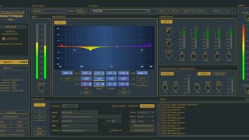
In switched-mode power supplies (SMPS), the switching element is typically a MOSFET. Paul Sagi, writing from Kuala Lumpur, Malaysia, was repairing a piece of pro audio gear that needed a new MOSFET. The old one had failed from overheating. These supplies also use a series RC snubber and Paul could not find the proper values of R and C from his parts supplier, so it was time to improvise.
Paul chose other values of resistance and capacitance having the same RC time-constant, same power dissipation rating and same voltage rating. The new combination worked well enough and the new MOSFET ran cool.
Paul has provided links to pages that explain some things about how to give a MOSFET a proper snubbing. They can be found at radioworld.com/links. Thanks, Paul, for a treasure trove of links.
Contribute to Workbench. You’ll help your fellow engineers and qualify for SBE recertification credit. Send Workbench tips to [email protected]. Fax to (603) 472-4944.
Author John Bisset has spent 44 years in the broadcasting industry and is still learning. He handles West Coast sales for the Telos Alliance. He is SBE Certified and is a past recipient of the SBE’s Educator of the Year Award.