Consultants Also Comment on Mobile Field-Strength Plots as a Measure of Performance
How can you get the most out of your FM antenna system? To provide some insight into this subject, three prominent broadcast consulting firms were asked to respond to 15 topics about FM antenna performance. Their earlier responses can be seen in previous issues of Radio World and online at under the tab “Better FM Coverage.”
The participants are Ben Dawson of Hatfield & Dawson; Bob Culver of Lohnes & Culver; and Don Markley of D.L. Markley & Associates.
Note that any consultant would need specific site and application information to provide an accurate recommendation for a given situation.
Topic: Comment on the validity of using one- or two-bay tests to extrapolate the final azimuth patterns of a complete array containing more bays.
Dawson: Such measurements are precise only when each element has the same mounting conditions and tower geometry within a wavelength or so. On small cross-section towers, the extrapolation of the data is, in the world of decibels, as accurate as needed for most situations.
Culver: If you have looked at the horizontal (azimuth) pattern variation vs. the mounting position along a support structure, and there is no significant variation of maxima or null position or depth, then the composite vertical array horizontal pattern will be the same.
A good way of estimating the final pattern would be to make several azimuth pattern measurements with the elements slid along the mounting support in several small steps (1/3 spacing, for example). The final pattern for a large array will be the average of all these horizontal patterns.
Markley: We have no problem using one or two bays to determine an antenna pattern. One bay is satisfactory if the pattern of a single bay is symmetrical about its axis. Many antennas are not quite symmetrical. For this purpose two bays can be used with one reversed and the phase controlled either by bay spacing or interbay circuitry.
Topic: Comment on antenna OEM standard practice, and results to the user/ listener, of measuring only H and V fields on a CP antenna, omitting all other polarization planes.
Dawson: Ideally the phase relationship should be determined, but it’s a price market.
Culver: The H and V field values are at their maxima, rather they deliver the maximum energy for a like polarized receiver antenna. There is very little possibility of de-polarization of the signal over the distance and propagation normal to FM radio. Of course the vertical polarized component is reversed in polarity (180 degree phase shift) upon reflection from an object.
The circular polarization field is generated by the 90 degree offset between the H and V polarized fields, which generate a rotating field orientation along the direction of propagation. It is “circular” only if the relative fields are equal. There is never a circular field, just a constantly changing linear field with position.
Measuring these two fields independently, H and V, is fine. Measuring the relation between the two with a constantly changing (rotating) linear receiving antenna vs. azimuth pattern angle will yield some additional information.
They have done this for C-pol TV antennas and call it the axial ratio, this is the ratio between the H and V polarization as the azimuth pattern is swept. By the nature of the display of such measurements, a sinusoidal wavy line around the azimuth, it is illustrating the independent H and V values, only reaching a maximum when the rotating receiving antenna is aligned with the transmitted field polarization.
I have done similar measurements but by quickly switching between the cross-polarized receiving antennas.
Markley: It might be desirable to take more than just horizontal and vertical fields. However, there would seem to be less and less to be gained as the number of such measurements is increased.
In any case, the polarization is going to become more and more random as the signal is filtered through trees and buildings.
Topic: Comment on the value of ground- and air-based mobile field-strength plots as a measure of the pattern performance of an installed antenna.
Dawson: Measurement data is really only valid as relative data, and it’s not always easy to wash out the ground reflection problems from aerial measurements. Both types can be useful for problem solving.
Culver: GI-GO: Garbage in, garbage out.
Now to explain this. You can measure the full-scale antenna to perhaps +/- 0.5 dB on a good range. For scale measurements the accuracy may be +/- 0.8 dB or so. Others may argue that the results are much better or worse, but how much, another 0.2 dB? My reason for saying this is the following.
You can measure the differential field from two antennas in the field with ground-based measurements to perhaps +/- 2 dB. That assumes you return to precisely the same measurement path under similar environmental conditions, and work to minimize all controllable variations and the only error is in making the measurement run and calculating the average field.
By differential I mean that two transmitting systems, nearly co-located can be measured to find the difference between them. You can make absolute measurements of one such source to less precision, the reason being that you may not be aware of time, environmental or other variations that would be disclosed in the differential measurements.
You can extrapolate these measurements back to the antenna performance by working the field-strength estimation process in reverse. Why do they call them F(50,50) curves? Because they are statistical averages and they cannot tell you what the exact field may be at any particular time or location.
If you can use other estimation processes, you can get a different answer. Better? Perhaps; but what error will be built in? At least 5 dB, most likely 8 to 10 dB, especially over moderately long paths. (If you are close you have the vertical pattern to deal with.)
The same thing applies to airborne measurements but with some added problems. First, how do you know exactly where you are? OK, GPS is accurate to a few meters but how fast does it update?
For that matter how fast does your meter and computer record the values and how far have you moved between the GPS record and the field record? We ran into this problem in doing some digital audio field tests and eventually came up with a system that made and recorded the field measurements in a few milliseconds so the measuring vehicle moved only a few centimeters at highway speed.
We made sequential but virtually simultaneous H and V pol measurements on the fly (so to speak). What are you actually measuring, what does your measurement antenna see, ground reflections?
OK, you fly at an altitude equal to the antenna (500 feet minimum rural altitude, and worse in urban and controlled air space) and a distance calculated to keep the antenna null(s) at the reflection angle.
There is a way around all this so that you might be able to just fly anywhere around the antenna and automatically make measurements and reject ground reflections and know precisely where you are in three-dimensional space so as to pattern the antenna on its mounting system. But it requires using a special test signal and active components on both the tower and in the aircraft. They do something similar in audio. No one has done it at RF yet (haven’t checked the DOD or NSA projects).
Measurements at ground level, 6 to 8 feet not 30 feet, can be done very fast and takes into account all of the local propagation effects that are part of the reception environment. This was done for some of the digital audio field tests.
Markley: We place no value at all on ground-based measurements to determine pattern performance. The effects of the terrain on the signal strengths are so significant as to eliminate any value of the measurements.
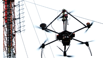
Carefully performed air measurements can provide good information regarding the pattern. To show the pattern itself, these measurements need to be done close to the antenna. We prefer a distance of two or three miles and to do the measurements with a helicopter.
Measurements at a greater distance are more affected by terrain and serve more to show the areas serviced than to actually determine the antenna pattern.


