If you’ve ever constructed a Tesla coil or watched a demo, there’s something fascinating about the steady stream of purple sparks that spray out from its discharge terminal, the noise of the spark, the smell of the ozone.
You’ll also likely realize you’re witnessing the step-up of a hundred volts or so into tens of thousands, and that the output of most coils (tabletop variety) is rather harmless, due to the limited current and high output frequency that channels most of the energy over the outer surfaces of living organisms — the so-called skin effect.
The Tesla coil is also a radio transmitter, embodying elements found in any such device — a source of oscillations and resonant circuitry — and a good case can be made for Tesla’s having “gotten there” before Marconi. However, according to Nikola Tesla, his invention was not intended as a device for wireless communication, but rather as a means of generating very high frequency alternating current that might be used for wirelessly powering homes and industry.
When the circuits of early radio transmitters (spark oscillators) and the Tesla coil are compared, there’s little difference, except for a coupling network for delivering the RF output to an antenna and an easy means for rapidly turning the RF generation on and off (keying).
At its heart, Tesla’s coil is a radio transmitter — but one that operates without communications as its goal and in an environment where corona discharge is welcomed rather than strongly discouraged!
In the 1920s, the advent of high-power vacuum tubes relegated the spark transmitter to the scrap heap. A 1927 international agreement officially banned the licensing of new spark transmitters after 1929; however, by this time, due to inefficiency of spark technology and the interference produced, few spark stations were still in operation.
MOVING FROM THE SPARK
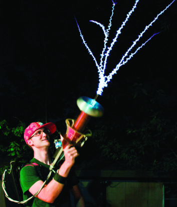
The Tesla coil also made the jump to the vacuum tube as a source of radio frequency energy, with a number of designs adopted by experimenters (and commercial enterprises). One of these is shown in Fig. 1.
While broadcast and other transmitter designs began to move away from vacuum tubes during the final decades of the 20th century, the Tesla coil lagged somewhat behind, as making such a jump involved much more than fitting a big transistor in place of the triode tube shown in Fig. 2. And due to the relative fragility of transistors, especially with regard to voltage spikes and other momentary disruptions that would be of little consequence to tubes, most Tesla coilers were content to stick with spark- or vacuum tube-excited machines.
Due to the dedication and engineering efforts of some coilers, solid-state excitation is now feasible, even in very large coils, and serious experimenters are beginning to feel the same way as broadcasters with regard to operating with anything other than a solid-state rig.
MAKING THE SHIFT
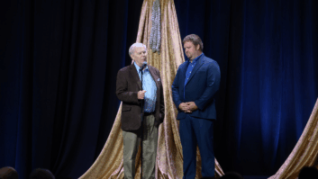
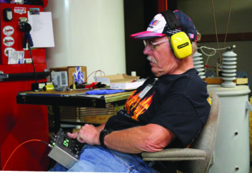
Readers may recall my story in these pages in 2015 about “super-coiler” Ed Wingate and his giant Tesla coil.
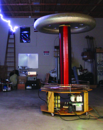
Wingate, a career tool and die maker with no formal training in electricity or electronics, has been interested in Tesla coils for most of his life and has constructed a number of them, reaching a pinnacle of sorts with a monster coil capable of delivering awe-inspiring discharges 10-feet in length or more.
In the article, Wingate, then 67, mentioned that he was intrigued by the possibilities of moving into solid-state technology, especially after locating some insulated-gate bipolar transistors (IGBTs) that could handle upwards of 1,200 Volts and were comfortable with currents of several hundred Amperes.
He has now made the jump to solid-state technology, finding that while it wasn’t especially easy or cheap, such a move is rewarding, as his new coil can do things the old one couldn’t (such as be modulated with tones or music).
NOT NECESSARILY AN EASY PATH
Wingate related that he decided to start out by purchasing a commercial kit for constructing a solid-state coil.
“It was a small DRSSTC [dual-resonance solid-state Tesla coil], and I was very disappointed with the performance,” said Wingate. “It would only do seven- or eight-inch sparks, and as the driver had no current limiting, it blew IGBTs quite frequently. I wound up with a whole can full of blown transistors, and it was a real pain in the butt to change them out.”
After giving up on the kit, Wingate sat on the sidelines for a while before testing solid-state waters again.
“I had become a skeptic about solid-state and was not really aware of what really could be done in that area,” he said. “However, I got an offer from a museum to build a coil for them and finally decided it was time to try again.”
Wingate points out there was no “kit” approach for a really big coil and his new solid-state device required several hundred hours to construct, spread out over some four to five years.
“I got the driver section and the bridge [output] all figured out and assembled, as well as the tank capacitance circuit, but then I sat on it for a couple of years. Finally, a friend nudged me to complete it, and I did so in about six months.”
Wingate observed that pulling everything together and getting the new coil “on the air” was made considerably easier, as there is now an established community of coilers who have moved to solid-state technology, and he was following in the footsteps of others who had learned where pitfalls existed. However, he stressed that getting there wasn’t exactly a “cakewalk.”
“There are no kits or even p.c. boards for something like this,” said Wingate, noting that the only area of the coil that is not hand-wired is in the output stage with the big IGBTs. This construction was facilitated by a design from another coiler.
“There are two copper plates used for mounting the IGBTs in the driver bridge that were designed by a young man named Philip Slawinski, and this is a very good design. The IGBTs are screwed down to heat sinks on these plates, and these plates are something you can’t just go out and buy.” (Wingate had his laser-cut from one-eighth inch copper plate by a local machine shop.)
[Teslathon Isn’t About Expensive Cars]
What about the big insulated-gate transistors themselves? Wingate admits that they sound pricey, but thanks to some Internet shopping, these and other specialized components weren’t all that expensive.
“I used four CM600HA IGBTs, which are rated at 600 Amps at 1,200 Volts,” he said. “When they first came out, they ran about $500 apiece. Now, you can buy them on eBay for about $20.”
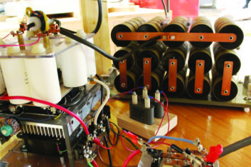
Wingate also shopped around for the specialized energy-storing capacitors that are part of his design.
“There are 75 of these in the tank circuit,” he said, noting that the Eurofarad pulse capacitors he purchased from a surplus dealer had likely come from a nuclear magnetic resonance imaging machine [MRI], and if new, would sell for some $200 each.
To get the necessary capacitance value (1.25 mfd.) and voltage rating (18 kV), Wingate arranged the caps in a series/parallel configuration comprising five strings with15 capacitors in each string.
“The whole capacitor bank weighs about 125 pounds,” he remarked.
Equally impressive are some of the electrical parameters of the IGBT coil. Wingate supplies the driver section with up to 720 Volts of DC from a voltage multiplier-type power supply fed directly from 240 Volt AC mains.
“There’s a total of about 23,000 microfarads of energy storage in the power supply. I run the power supply with a Variac to bring the voltage up slowly, as there’s something about plugging 23,000 microfarads of capacitance into the AC line that scares me a little.”
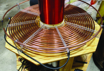
He notes that “current limiting on the driver board is set at 2,500 Amps, which may seem extreme for 600 Amp-rated transistors, but it’s pulsed.” RF potential on the primary of the coil (constructed from large diameter copper tubing) is estimated to be around 10,000 Volts.
Even by taking a “bargain basement” approach to components (the five-foot-high, 10-inch diameter PVC coil form was originally intended for plumbing purposes) and using items already on hand, construction of the IGBT coil was not a trivial expenditure.
“The whole thing came in somewhere between two and three thousand dollars,” said Wingate, adding that this was probably close to what he’d spent on his earlier big spark gap-excited coil.
A NEW FRONTIER
As Wingate had been content with his spark-driven coil for several decades, what was the incentive to go solid-state?
“I wanted to try something new as far as coils went, and solid-state was the ‘final frontier,’ something I’d not gotten into yet,” he said. “There is also the efficiency and control you have with a solid-state coil.”
Discharges delivered by the new coil are as impressive as those from his earlier model, and there’s also another “enhancement” that’s not possible with a spark gap type machine. This is the ability to modulate audio on the RF pulse train powering the big coil.
Recognizable sound is produced by the rapid heating and cooling of the air around the discharge, just as with lighting and accompanying thunder. While not exactly “hi-fi,” varying audio tones, music and even speech can be output with this sort of drive system. Wingate says that he’s never tried speech, but does play recorded synthesizer music as part of his demonstrations of the new coil.
Now that he’s arrived in the solid-state world, has Wingate abandoned his spark-powered coil? “No, it’s still ready to run at a moment’s notice,” he said.
And just like the earlier device, the IGBT-driven coil is by its nature a very powerful generator of radio frequency energy. Wingate is mindful of this, with the bonding and grounding of all sections of his metal Tesla laboratory building, and the installation of powerline RF filters. As he observed previously, “My entire lab is a Faraday cage.”
Comments From a Designer of Large Solid-State Tesla Coils
Steve Ward, an Austin, Texas-based electrical engineer who specializes in embedded power electronics, and is well-known to the Tesla coil community for his solid-state design contributions, provided additional information on the performance of Wingate’s new coil.
As measured with the “top hat” capacitive toroid in place, the resonant frequency of the primary of Wingate’s coil (Tesla “transformer”) is about 27 kHz, and the peak power (we’re dealing with pulse, not average power here) runs in the neighborhood of one megawatt (600 Volts x 1,750 Amps). As the pulse duration is in the tens to one-hundredths of a microsecond range, he calculates an average input power on the order of 20 kW.
Ward points out that in the design of large Tesla coils, a couple of factors involving the winding conductors limit overall efficiency. The first is the “skin effect” encountered with high-frequency currents which causes most of the current to flow on or near the outer surface of the conductor. He estimates that power losses due to “skin effect” limit efficiency to between 70 and 80%.
A second factor is the “proximity effect,” which stems from the influence of the magnetic coupling between coil windings. The effect is to reduce current flow in adjacent windings to flow within a smaller subsection of the conductor, further reducing their useful current-carrying area.
Ward also points out Tesla coils aren’t very efficient radio transmitters, as they aren’t able to radiate much of the RF energy produced due to the classic situation of poor free-space radiational efficiency that results with an electrically short antenna.
“Very little of the peak power making it to the output of the Tesla coil can be radiated as RF energy,” said Ward. “The operating wavelength of the coil is very long, yet the coil is relatively short at just several feet high — perhaps two meters. At 40 kHz, a quarter wavelength is about 1,875 meters. The VSWR is very high.
“If it were not for the sparks eating up nearly all of this energy, most of it would be returned to the DC power source feeding the H-bridge via rectification. In radio engineering terms, the impedance match is very poor!”
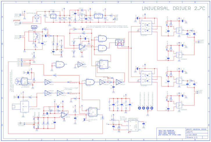
The Big Coil’s Solid-State Circuitry
As mentioned, there’s a lot more to creating a reliable solid-state Tesla coil than replacing the power triode in the vacuum tube circuit (Fig. 2) with a transistor. As evidenced by the schematic of a large portion of the coil (Fig. 4), there’s a great deal more involved!
In very basic terms, the solid-state coil’s inner workings may be described as follows:
A square wave pulse train with an adjustable duty cycle is generated by the “interrupter.” (Circuitry is based around the “old reliable” NE555 timer i.c., and is contained in a hand-held metal enclosure that’s physically and electrically isolated from the high-power portion of the coil by fiber optic connectivity. It’s powered by an internal 9-Volt battery.)
The pulse train arriving from the “interrupter” feeds a “driver” stage that generates gating pulses for switching the high-power insulated-gate bipolar transistors (IGBTs) on and off. (Both coil designer Ward and fabricator Wingate point out that switch timing is critical to successful operation — and longevity of the IGBTs — as the silicon devices don’t like to see large voltage spikes or overshoots from pulses arriving at the wrong time. “You really have to have an oscilloscope to ‘tune’ the coil,” Wingate observed.)
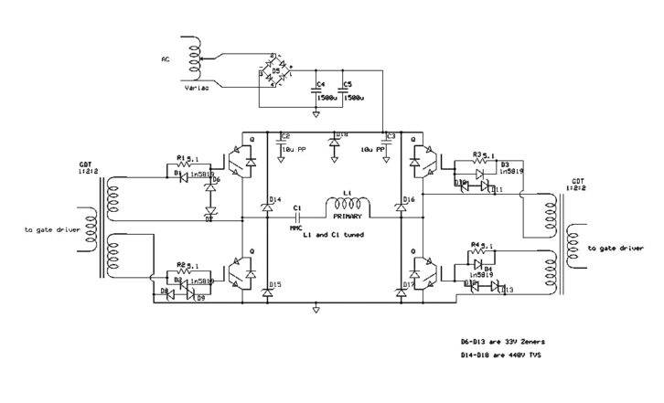
The timed pulses from the driver control the switching of the IGBTs in the “bridge” or “output” stage of the coil (Fig. 5). Ward notes that two different IGBT configurations are commonly used in solid-state coils — a balanced “H-bridge” with four transistors, or a “half-bridge” constructed with two IGBTs. (Wingate’s coil uses H-bridge architecture. (See Fig. 5.)
The gates of the IGBTs are driven by output windings of the two transformers configured in such a way that the left and right pairs of IGBTs operate in a “push-pull” manner. The devices feed the “load,” which is the primary winding of the Tesla coil in series with a capacitor that’s selected to form a series-resonant circuit at the desired operating frequency (in the case of Wingate’s coil, around 27 kHz).
As seen in the drawing, Ward’s output stage design includes a number of Zener diodes, including four large 440-Volt devices, to protect the IGBTs from overvoltage conditions and high-frequency voltage spikes.
He also notes that in the design and construction successful large solid-state coils, keeping parasitic oscillations — and the RF voltages that could arise from them — at “ultra-low levels” is absolutely essential, and was a concept not initially well-understood or appreciated by the Tesla coil community, when some coilers began experimenting with solid-state designs a number of years ago.