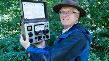
Most of the time I sit behind a desk these days, shuffling paper, crunching numbers, working the e-mail and talking on the phone. But once in a while I get out in the field to do something interesting. I had such an opportunity in late October.
In the process of preparing an FCC application to relocate one of our AM stations to a new site, I found that I needed a span of measured conductivity data that I didn’t have. In every other direction of interest I had data from an old (1990s) facility that had once occupied the Southern California site we purchased a few years ago. But in one direction, toward the contour of a nearby third-adjacent station, I had no data.
The FCC’s M3 conductivity data showed a very high value that I knew was not correct. Without the measured data, I would have to roll the power of our relocated station way back. And so it was that I found myself in the position of needing to set up a test transmitter at the site and make some radial field strength measurements.
The process for doing this is fairly straightforward.
First, we had to find a frequency. That was fairly easy. I looked at the daytime allocations at the top end of the band and found that on 1690 kHz there was nothing co-channel for a long way in any direction. There were first- and second-adjacent channel stations within a few hundred miles, but nothing close enough to matter.
I filed an application for special temporary authority for 1 kW on 1690 kHz from the new site and quickly got a grant.
GATHERING THE GOODS
Next, I had to round up some materials.
Bill Agresta, our chief engineer in the market, was able to find a supplier of Rohn 1-1/4-inch steel mast sections, and he purchased 10 of those. He then found the nylon guy rope we would need, 1-inch rebar (for guy anchors) and miscellaneous hardware at Home Depot.
Since Bill is somewhat of a packrat, it was no surprise that he had in his possession a porcelain bell-shaped insulator from an old railroad telegraph pole that would work just great as a base insulator.
I had in my secret stash a couple of 2,000-foot rolls of AWG #12 bare copper radial wire, so I shipped those to California along with my recently-calibrated field intensity meter (FIM). Our friends at Nautel Ltd. have a J1000 1 kW solid-state AM transmitter that they make available for rent, so I arranged to have that tuned up on 1690 kHz and shipped.

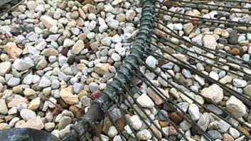
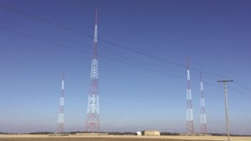
Left: Antenna base, bell insulator, ground ring/radials and tuning network. Right: The antenna had an ‘S’ shape at times, depending on the wind!
Finally, my good friend Joel Saxburg, assisted by local engineer Burt Weiner, came up with the materials to make an antenna tuning unit that should match just about any low-Z load. Joel and Burt cobbled the ATU together on a piece of particle board, complete with J-plugs on the input and output and a female N-connector on the input.
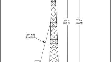
In the weeks leading up to the measurements, I had played with a number of antenna designs and models, and finally settled on a 50-foot vertical mast with 30 feet of guy-wire top-loading. I felt that height should be physically manageable, and the top-loading, which would consist of 30-foot lengths of the bare AWG #12 wire connected to the top of the mast and taped to the top set of nylon guy ropes, would produce a base impedance that we could work with.
We scheduled a three-day period in which to conduct the measurements. Day one was designated as setup day, and Bill arranged to have a portable generator delivered to the site that afternoon. He also had a crew of 12 on hand to assist with the assembly and raising of the antenna.
IN THE AIR …
On the advice of a long-time friend and consulting engineer, I initially had planned to assemble the entire antenna and then raise it up by using several people along its length along with a number of others manning the guy ropes. Because the site has some slope to it, we were able to lay the assembled antenna on one of the sloped areas so we wouldn’t have to pull it vertical from flat on the ground.
Like all great battle plans, that one went out the window as soon as the first shot was fired … in this case, as soon as we tried to raise the antenna. We didn’t buckle anything, but it was apparent we were headed that way. The mast material we were using must have been a lot more flexible than what my friend had used. We needed a better approach.

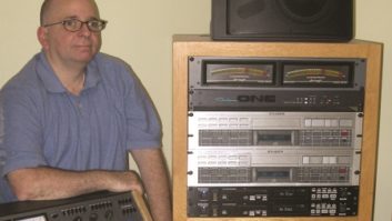
The author adjusts the tuning network as Joel Saxburg, Burt Weiner and Todd Stickler, from left, look on. Kyle Warner is at far right.
The new plan was to assemble 30 feet, raise it into the air (one person could do that) and have people man the guy ropes while we lifted the whole thing straight up and inserted additional sections from below.
That procedure worked like a charm. The hardest part was installing screws at the joints to create the good electrical bond we needed. We then lifted the entire mast and set it on the bell insulator.
AND ON THE AIR
Finally, with the antenna in the air and guyed off (and shaped like the letter “S”!), I got busy laying the ground system. I rolled out a dozen 165-foot lengths of the AWG #12 bare copper wire on top of the ground, securing the ends with spikes. Bill used a piece of 1/4-inch copper tubing as a ground ring and soldered all the radial wires to it.
Next, we measured the base impedance of the antenna and found it to be 26.5 –j231 ohms, a value we could easily work with. We then connected the ATU network Joel had built, calculated the leg values and set them with a bridge. Checking the input of the network we should have seen 50 ohms. What we saw was anything but! We spent an hour trying to get that network to match the antenna in both tee- and L-network configurations without success. With the sun rapidly going down we packed up and headed down the mountain for the night.
(click thumbnail)
Detail picture of homemade ATU. Note the large coil mounted over the ground strap, which added unexpected capacitance. The next morning we attacked the tuning network again. Like the night before, nothing was making sense. The laws of physics and electronic theory should apply, but in this case they appeared not to.
We had just about run out of altitude, airspeed and ideas when the light bulb came on. To give us lots of adjustment range, Joel had employed a large (several hundred microhenry) coil on the output of the network. We were using only about a third of it, and the remaining turns were left open. Our problem was that the unused turns of that coil had a lot of distributed capacitance to the 6-inch copper ground strap running beneath the coil and it was acting like a large capacitor to ground across the base of the antenna!
A few circuit modifications and we quickly had a 50-ohm non-reactive load for our transmitter. We connected the J1000, fired it up at 1 kW and were off to the races.
We had a little generator trouble, something with the governor; but that eventually straightened itself out. We used a 360 Systems Instant Replay to loop a 1 kHz tone and voice ID into the transmitter at about 50 percent modulation so that we could identify the signal in the field, particularly at the far end of the radial where the signal would be weak.
A WALK IN THE WOODS
There are two components to any set of AM field intensity measurements for determining ground conductivity: close-in measurements to establish the inverse distance field (IDF) of the antenna, and far-field measurements to determine conductivity. The FCC wants to see at least seven measurements inside 3 km, but more measurements make it easier to analyze the data.
I, along with my daughter Amanda (chief engineer of our Denver market) and our local operations manager Todd, started off on foot for the close-ins. We used a handheld Differential GPS/Wide-Area Augmentation System-equipped GPS unit to keep us on the radial and determine the exact distance back to the antenna. Starting at 50 meters we made measurements every 50 meters or so out to 400 and then every 100 meters out to 1 km. Beyond that distance we got what we could.
Most of the area is located in the Cleveland National Forest. The name evokes images of stately lodgepole pines and aspens. Picture instead scrub oak 10–12 feet tall and so close together that we couldn’t squeeze between them. We had to follow game trails through the dense brush in many locations, pushing back into the scrub to get the measurements.
We finally reached a point where there was a sheer drop-off of several hundred feet lined with more of the same dense brush. It became clear that this was the end of our close-in measurements. We climbed back out, hiked to the nearest trail and began working our way back to “base camp” where we spent hours digging the tree “stuff” out of our pockets, collars and waistbands.
While Amanda, Todd and I were having fun in the woods, Joel and Burt were out on the road taking far-field measurements. It didn’t take too long to go as far as they could — they hit land’s end just north of Ranchos Palos Verdes and called it a day.
It was with some sadness that I signed off our one-day test station. We took the antenna down and packed up all our stuff, leaving the site as pristine as we found it. Back in Denver I was able to analyze the data and prepare a showing for the FCC. It was a lot of trouble to determine the conductivity over a 70 km path on a single radial, but in the end it will be well worth it. And for about five hours on that one day in October there was a signal in the L.A. area on 1690 kHz.
Cris Alexander is the director of engineering at Crawford Broadcasting and a past recipient of SBE’s Broadcast Engineer of the Year award.