Last March the author described a project to replace the AM tower at KJNP in Alaska (“Hands On: Replacing a Tower at North Pole”). In this installment he describes the culmination of the project.

After KJNP’s replacement AM tower was constructed, we began the work on the lights and static eliminators.
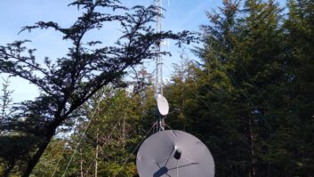
We are using Medium Intensity Dual Obstruction Light Standard E2, which has red lights at night and white lights during the day. The LED lights from Slatercom were mounted on the tower by Nolan Brothers.
The power to these will run through a Austin-Ring transformer at the base of the tower. With the long power run from the building, we are operating the Austin-Ring transformers with a 240 VAC primary. We operated the lights with a direct AC connection while installing the Austin-Ring transformer. These have a ball gap to install in addition to the ball gap over the tower base insulator. Nautel has a downloadable ball gap spacing utility that we used to set the initial gap to 3/4-inch.
The system originally was set up for incandescent lights operating at the beacon with 120 VAC; with the lower current draw of LED lighting, we now have 156 VAC on the tower base. The new tower lights have an operating tolerance of 100 to 277 VAC, so we did not need to change anything from the original configuration.

We also have power to the ATU for the current meter and heat. With temperature swings from 80 degrees F in the summer sunshine to -60 degrees in the dead of winter, the tuning of the ATU can change. We have the unit insulated with heat to maintain a stable temperature. There is also a utility power outlet at the tower base.
The lights were installed with an ice shield above the side-mounted lights. Each light has a built-in level to make it easier to install correctly.
Originally, the tower light monitor antenna was on the bottom of the enclosure, but we found it was getting some moisture in it. We drilled a different mounting hole on the side, and put a drain/vent in the home in the bottom of the enclosure. Drilling the stainless steel was not easy, but it resulted in a better location for the monitor antenna, even though it is not as protected from falling ice. Because this is an insulated tower, we are using a radio signal to get the tower light information back to the station building.
For the center feed, it was installed in 10-foot sections. The sections were made of 1-inch water pipe silver soldered together. As a section was added on, the tower crew would raise it 10 feet inside the tower, then I would solder on another section. This goes up 150 feet, then attaches to the tower legs with copper strap from the pipe to the tower legs. It is distributed through six clamps. There are supports every 10 feet to keep the feed centered in the tower.

GROUND RADIALS
While the tower was down, we used a transit and tape measure to set stakes for the ground radials. There is a 30-by-30-foot screen around the tower base and the radials are hooked to that.
We put a sub-soiler on our tractor three-point to pre-rip all the radials, so that when we trench in the wire we would not run into problems. This was done by using a pipe with a sweep elbow bolted to the rear of the sub-soiler to feed the into the ground when actually trenching in the wires.
Some areas still needed to have hand-dug trenches. These were areas where we could not get our tractor through because of space, and where there were underground wires to avoid.

With these steps done, we mounted a stand on a trailer pulled by the ripper to feed the wire into the ground.
After putting in the radials, we put a 3-inch copper strap square around the tower base at 30 feet to hook the radials to, the inside of the square is 1/2-inch copper mesh. All this was put together with silver solder. The number of connections to solder made this take a lot of time.
We put dirt over the copper ground mat. The radials were connected to the outer edge of the mat. After the dirt we put down fabric to stop the weeds from growing. On top of that is crushed rock.

The ATU was put back into place and connected to the ground mat. The coax hooked back up, and the tower feed point hooked back up. The feed point is a 1-inch copper pipe inside the tower, insulated to the 150-foot point where it connects to the tower. This was done on the original tower to prevent arcing over the base insulator.
We wanted to make the replacement as close to the original as possible, since that tower was working fine, except for mechanical issues due to age. However, we did update to a galvanized tower with updated obstruction lighting to minimize future maintenance.
TUNING
Tuning the tower took some time. It has to be done when the standby antenna and tower are not operating, so we did it at night.
We used a signal generator and Delta OIB-1 bridge to measure and sweep the tower, then to set the coax input to 50 ohms. After setting everything with a signal generator we put the transmitter on at 5,000 watts and checked the measurements. These measurements were used to calculate our power level with the base current meter in the ATU.
The original tower was 185 ohms, the replacement tower is 190 ohms, so we were able to make some small changes to the tuning in the ATU to make everything match. Over the next week, we brought the power up to 50,000 watts.
There is a panel just outside the screen with the electrical panels and junction boxes. The wiring was retained from the original tower, so we did not have to replace the wires and coax in the ground.
We put the station back on the air at 12,000 watts for a couple of days, them moved up to our low-power nighttime operation of 21,000 watts. A few days later we moved to 35,000 watts daytime, then to our license power of 50,000 watts daytime. While slowly increasing the power, we also monitored for hot spots, arcs or anything that looked like a potential a problem.
After getting back to normal operations, we took down the standby antenna and put it away. We also rebuilt the fence around the tower base, so everything is back to normal.
We have received listener reports from Bethel and Anchorage and confirmed coverage at Dot Lake, which shows a coverage area of more than 300 miles; KJNP(AM)’s signal is as good or better than when we started.
Radio World wants your first-person project stories. Email [email protected] to learn more.