While it hardly qualifies as cutting-edge technology, the project described here did provide a solution to an annoying problem I have faced several times: How do you get a decent off-air signal from an AM station, where the studio is in a modern curtain-wall office building and is located at or beyond the 5 mV/m contour of the station?
I saw evidence that several engineers had explored solutions in the past. The hardware was still around when I arrived. A very nice (and pricey!) commercially-made shielded loop was installed on the roof with inside phantom power for its preamp in the studio racks seven floors down. That didn’t really work. A better antenna signal could be had from the coax shield than from the actual loop antenna and preamp output.
Another iteration was the installation of pre-amplified loopstick antennas, taped to the window glass in one of the studios with coax routed back to the rack-mounted receivers. This, too, yielded a marginal signal — enough to tell if we were on the air, but not useful for critical evaluation at all.
Yet the stations both had very usable, listenable signals on my car radio parked in the building driveway.
A COMMON PROBLEM
As is always the problem with metal-skinned buildings, the openings in the exterior walls behave like sections of waveguide at frequencies below cutoff — virtually all of the field is cancelled. I concluded that no inside solution would ever work satisfactorily. Long runs of coax also weren’t working.
How could the car radio result be replicated in the building? To do that, I borrowed old technology and married it with some moderately-priced new technology to build what I believe is a solid solution.
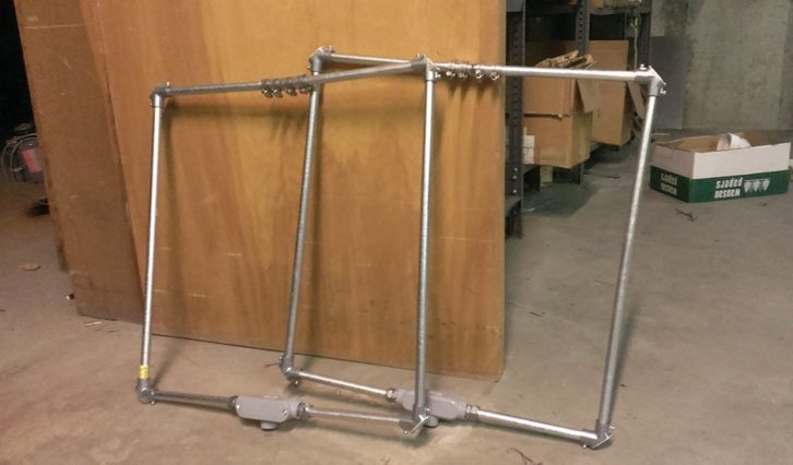
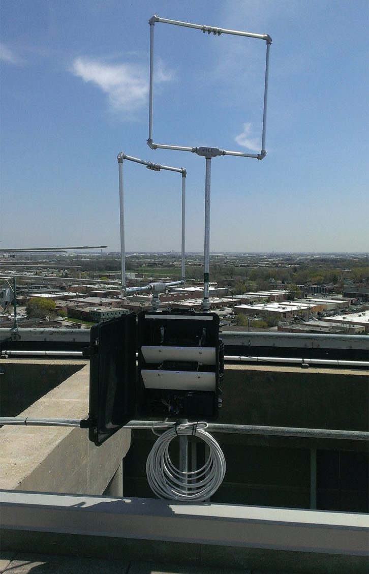
I fabricated two shielded loop antennas from home center components as shown in Fig. 1. Inside the tubing is 10 turns of ordinary hookup wire. I used some multi-conductor wire and joined the ends to make one long wire length (see Fig. 2). Recall that the purpose of a shielded loop is to make the antenna responsive to only the magnetic component of the transmitted signal.
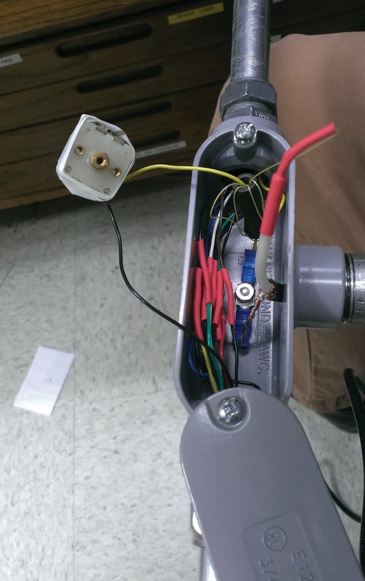
The shield is there to prevent successful capacitive coupling with electrostatic fields. Since the electrostatic fields from AM stations (and from most sources of interference) are vertically polarized, the electrostatic field induces voltage in only the vertical pieces of conduit. That same electric field exists inside the tubing as well and induces a voltage on the wire turns inside.
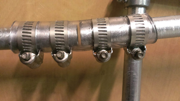
So how does this shielding help? Because the electric field in the vertical tubing sections induces voltage in the wire turns in opposite directions on either side of the loop. Thus the electrostatic contribution (in a perfect world) cancels. The gap in the conduit at the top of the loop (Fig. 3) is to avoid having the shield look like a shorted transformer turn, thus cancelling the magnetic component as well.
This is how your field intensity meter works. Regardless that the meter scale is calibrated in volts per meter, it is a magnetic device. The relationship between the electric field and the associated magnetic field is a known constant (120π)t and the Potomac folks figure you won’t be using the meter in other than an air environment, a pretty safe bet. Loop orientation works just like your field meter as well, with distinct nulls and maxima as you rotate it.
To provide just a bit of pre-selection to the loop, I added a small transistor-radio-style variable capacitor bought from an eBay seller. I calculated my ten turns to have about 200 microhenries, but with the capacitance contributed by the tubing and other unquantifiables, who knows?
My variable cap has two sections, each about 220 picofarads. I paralleled the sections and wired loop and capacitor as a tank circuit — the miracle of adjustable components. Just turn the dial until it works! Tune for maximum smoke. The result is a broad resonance, but helpful for me, since my location is in the 50+ mV/m field of two other AM stations.
To couple each loop to a receiver, I used some randomly chosen ferrites found in a drawer and made a small ferrite loaded transformer for each loop antenna. I figured the impedance of the loop would be low. I guessed maybe an ohm or two. So, a 1:5 turns ratio would get me somewhere in the 50-ohm neighborhood.
NON-CRITICAL DESIGN
As you’ve probably guessed by now, nothing in this design is particularly critical. The radios are ordinary Panasonic in-dash models bought on eBay for about $20 each. This, too, is anything but critical.
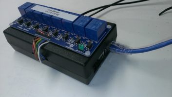
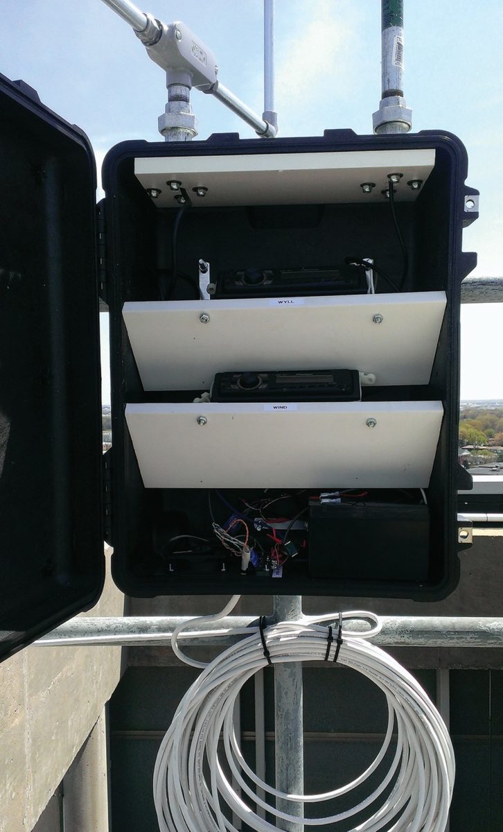
Now, with two steerable antennas, I have a decent signal from both stations. But how to get that RF down seven floors to the studio? The answer is not to try. Instead, I installed my two car radio receivers in a weatherproof box (see below) and clamped the whole business to a railing on the roof.
The signals from two AM stations, as well as power, are carried on a piece of Cat-6 cable following the telephone riser path down the seven floors and into our leased space. Power comes up on two paralleled pairs, and baseband audio is coupled from the radio speaker outputs on the other two pairs.
The radios I used are bridge amplifier designs, meaning that the speakers are driven in a balanced, differential way, but I used small audio transformers for isolation anyway. Preserving balance yields undiminished audio quality downstairs. I also added a local headphone jack for each, allowing confirmation of proper operation before leaving the roof.
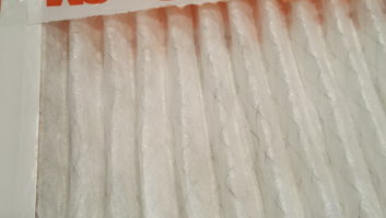
The whole business was installed into what Amazon calls a “black, tactical, weatherproof case” as shown in Fig. 4. We’ve all seen these used for sensitive electronics that must be shipped. They have snap locks and gasketed lids. I just ordered a generously sized one and installed the shelves you see. The loop antennas attach using ordinary 3/4-inch plumbing components with the antenna coax fished through. I added reinforcement where the pipe flanges attach. Finally, the whole assembly is U-bolted to the railing.
WHAT ABOUT POWER?
Powering the system remotely involved a little I-squared-R thinking. The Cat-6 run overall was about 250 feet. Paralleled Cat-6 conductors at that distance worked out to be about 5 ohms overall. I had no idea what current the radios drew and, barely visible in the pictures, is a small lead-acid battery also in the enclosure. It’s there to hold up the radios’ channel memory if the downstairs power needs to be disconnected for some reason. It needs to remain charged.
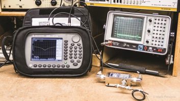
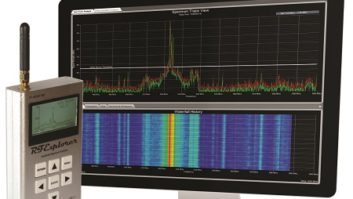
Finally, there’s a small 12-volt fan in the box as well. I guessed 2 amps for the radios which, with 5 ohms on the way, means my 12 volts will be 2 volts on the roof. I could have done some bench measurements and built a supply, but when I can buy a 30-volt 3-amp adjustable supply with metering and overcurrent protection on Amazon for $60, why bother? The supply is pictured in Fig. 5.
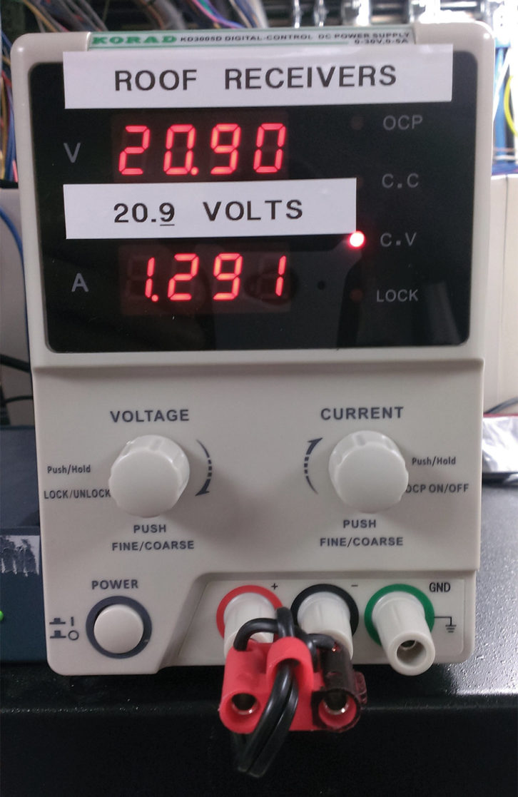
With the battery disconnected, the supply voltage was gradually raised until the receivers saw about 13 volts. I then noted the current. When the battery was connected, the voltage came down to about 12.8 and the current increased by about 50 milliamperes. That seemed a reasonable amount for trickle charging one of the 7 amp-hour batteries commonly used in UPS devices. We’ll see.
Anyway, the completed project, which is shown in Fig. 6, was simple, straightforward, not too terribly expensive, and solved a long-standing and annoying problem. For engineers it doesn’t get any better than that.
Frank McCoy is chief engineer of Salem Communications’ Chicago cluster. Got an idea for a hands-on engineering article? Email [email protected].