Like a lot of projects, this one started with a need.
One of the Chicago stations that Salem owns has separate sites for day and night modes. One site needs to go off and the other comes on simultaneously. Both sites have older remote controls with system clocks that drift. Plus, Daylight Saving Time is hard to account for because of the limited number of events that can be programmed in the remote control.
A previous engineer had installed two of the Broadcast Tools GPS event controllers, and all was well for a number of years. Then one failed.
The symptom was erratic command execution at random times. The night facility might suddenly pop on in the middle of the day. The fault was easy to see, too. One of the segments of the LED time display, representing one bit of the CPU output, flickered erratically every once in a while.
Because the design has a single data buss running everything from display to commands on a time-multiplexed basis, those flickers occasionally hit the contact closure drivers and strange things happened at the site.
I thought the fix would be straightforward, since I knew which data bit was misbehaving. Broadcast Tools cheerfully provided a schematic and I began diagnosis.
This meant lifting the IC lead associated with that data bit on every item the data buss serves, then waiting for the misbehavior. I had to set up a relay trap to catch the behavior, since days might pass between episodes. At some point, I abandoned the process and declared the Broadcast Tools GPS to be a goner. So that’s where the need arose.
Broadcast Tools doesn’t make that device anymore, probably because more modern remote controls support Network Time Protocol (NTP) and have highly accurate clocks. Not for the first time, I was a technology orphan.
Solving the Problem
Enter the Raspberry Pi. What I needed was a generic GPS-referenced time server that I could use to issue commands with basic relay dry contact closures as the interface. This is one way to do that.
This project uses the Raspberry Pi 3B and assumes you have installed a Linux operating system on your Pi.
Jessie Lite is the distribution I have used for this. There are a hundred sites that explain this, so I won’t do that here.
I will suggest that loading a Linux image with all the graphical user interfaces is probably a waste. In addition, I have found that code writing and compilation for the Pi is best done on the Pi itself and using the command line. Fancy IDEs just take too long to get working right. Use the little editor nano that is installed with Linux. Just my opinion.
Starting with the time part of the project, the Raspberry Pi has a system clock, required for OS operation. I haven’t measured it, but the reports I’ve seen put Pi system clock drift at 15 seconds a day. This isn’t useful for my purpose without help. But the Pi can sync itself using NTP and the vast array of available internet time servers, providing it maintains an internet connection. That might be all that’s needed for many applications.
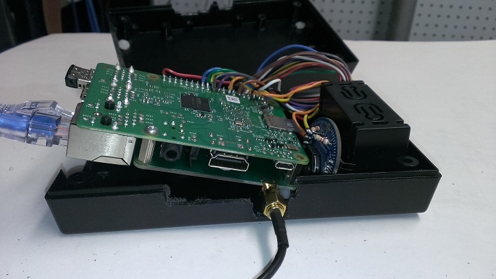
In my case, I can’t be assured that there will always be a reliable time reference. So I bought a Uputronics GPS Expansion Board that mates with the Raspberry Pi I/O header. They sold me an antenna as well. The board uses the serial UART pins on the Pi and issues a pulse every second when locked. In turn, these pulses trigger a CPU interrupt that “trains” the system clock.
Because the system clock is part of the OS and has no provision for an external sync pulse, the first significant undertaking was recompiling the Linux kernel to add that capability. (To obtain these instructions, just email [email protected] with “Please send me the McCoy instructions.”)
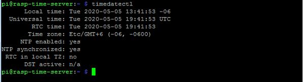
If successful, you’ll have built a Stratum 1 NTP server. This implies accuracy of just one or two milliseconds.
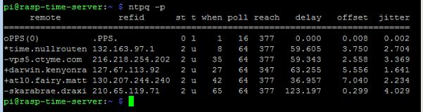
Read up a little on Linux ntpq, the time query language behind NTP. The command ntpq – p will report the success of timesync. That and the blinking green light on the GPS receiver card are excellent comfort monitors.
In my case, I worried that the GPS signal might become impaired. And if the Pi was headed to a place without internet, a one-second pulse really won’t help unless the Pi gets the right time set initially. Travel to the installation site might be enough to screw things up. So I added a real time clock.
This is a Chronodot, with battery backup (eight years, they say) and 5 seconds per month precision. If I sync the Pi and the Chronodot to the time server here at the studio, the drive to the transmitter shouldn’t introduce meaningful error. And the Chronodot can be set to the system clock — synced by the GPS pulses — on a regular basis, as insurance against simultaneous internet disconnection and GPS reference loss.
EBay Helps Out
Next up is the I/O to allow actions to be initiated by the Pi. The Raspberry Pi CPU is a 3.3 Volt device with not much current handling capability. I decided not to try to find out just how much.
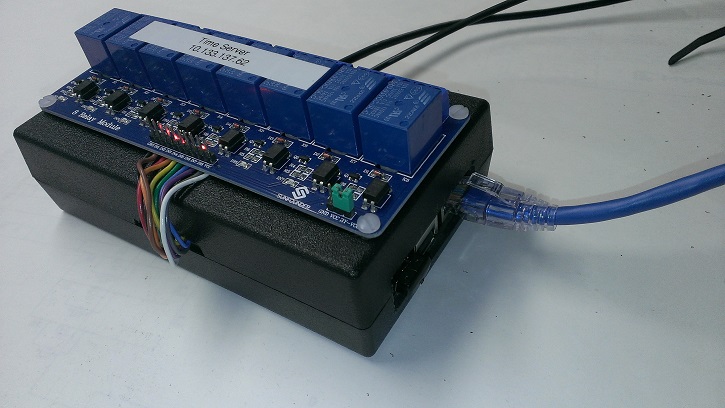
On eBay, I found a batch of 50 5-volt SPDT printed circuit relays for about 50 cents each and bought them. Like lots of eBay parts, these were a little weird and didn’t exactly fit on a .100 hole spacing kludge board (see photos), but with a little hole reaming and folding over the wiper contact, they would solder. I put eight on the board.
Paranoia about semiconductor failures drove me to install a diode in series with each logic lead from the Pi. Microprocessors don’t like to have their I/O pins dragged outside the CPU supply rails, and the relays need 5 volts. Another diode in the emitter lead guarantees the surplus 2N2222s turn off reliably. I bought a bag of 500 of them in the TO-18 (metal) case about seven years ago and still have a couple hundred left. (Later, I found this preassembled relay array complete with driver FETs.)
For ease of testing, I put an LED for each relay alongside the transistors and wired the logic to the 40-pin header on my Pi. A more elegant solution would have been to install a header and use ribbon. Instead, I found some cable with the EIA color conductors inside, stripped the jacket and tacked them to the solder side of the Pi header for connections to 5 volts, ground and the CPU’s GPIO outputs. Having a known working IO device on the Pi makes debugging easier.
There is a protocol and development environment including C language code headers for GPIO compilation at wiringPi.com. Follow the instructions for installation. Get the sample code “blink” to work. It’s the “Hello World” of GPIO. Then you’ll have proofed your compilation process.
After that, the compiled program I wrote takes arguments from the command line used to call it. All that is needed is which relay number, whether pulse (and duration), latch or release. I use the inbuilt scheduler CRON to issue the commands. CRON executes shell scripts (.sh) for each needed function. The scripts have readable names like TxOn.sh. These scripts, in turn, call my program with the appropriate command line arguments.
I noticed right away that CRON alone wasn’t precise enough, time-wise, for some commands. Scheduling with CRON is only precise to the nearest minute. Typically, commands experience a latency of about 2 to 3 seconds from the CRON scheduled time. For a mode change between sites, this just wouldn’t work. So I added some code that, upon program launch, loops while checking the system clock seconds value for a match, actuates the relay, then exits. In my case, a time with seconds = 00 meant the program had to be called by CRON and the script in the previous minute. So for 5:00:00 a.m., the command executes at 4:59 and loops until the system clock seconds equals 00, executes the relay action, then exits.
This whole process could be designed as a program that runs continuously, perhaps reading a text file at launch for the actual schedule of command events. But I like CRON. It might be the oldest remaining component in UNIX and is highly reliable. And using a simple program that performs and exits nearly immediately means the operating system and time functions have unfettered access to the CPU.
Even if you don’t need commands performed but just need a bulletproof NTP time server, this will serve well. Your port 123 needs will be millisecond-accurately served.
Got a project article in mind? Email us to suggest: [email protected].
Read another project by Frank McCoy, “Receivers in a Box on the Roof,” from December 2019.