Audio passed from lips to ears over short distances before the advent of radio. Broadcast changed that by using electronics to transport audio over great distances.
As you know it starts with a microphone. That clever device converts mechanical sound energy of vibration in the air into electrical energy. It is not magic, just good basic science.
I won’t go into the many microphone types, but it is important to understand that broadcast engineers must deal with sound as electricity.
How is audio electricity different from 120 VAC power?
In the analog audio world, microphone and program audio are very low in voltage of alternating current (AC) power. We typically think of audio frequency range as 20 Hz to 20 kHz, but to be practical, FM audio goes up to just 15 kHz while AM is 10 kHz. A typical dynamic microphone has an output of –50 dBm. That is 50 decibels below 1 milliwatt of power. It is so small that an amplifier is required just to bring it up to a level that can be worked with.
Tube and then early transistor audio amplifiers contributed unwanted artifacts such as noise and distortion that colored the sound. Today we have wonderful electronics to keep audio pristine sounding — assuming it is all setup and operated correctly. (See my article on audio levels.)
Just one device in an audio chain can degrade/ruin the sound if incorrectly adjusted. There is almost no fixing it after that.
Dynamic range
Today’s broadcast audio devices usually have 90 dB or more of range between residual noise, known as the noise floor of the equipment, and peak clipping. Audio between those two limits will be amplified cleanly. Before deregulation, FCC rules required FM broadcast proof of performance measurements to show at least 60 dB of dynamic range between 100% modulation and noise. It was only 45 dB for AM.
More is not better
I’ve written about this before, but it bears repeating. The most typical example of mistreating audio is running levels too high. You’ve seen it when announcers are recording or at the controls of a show. Enthusiastic operators often believe that “more is better” when it comes to setting audio levels. They crank it up, making the VU meters go into the red, to make it louder!
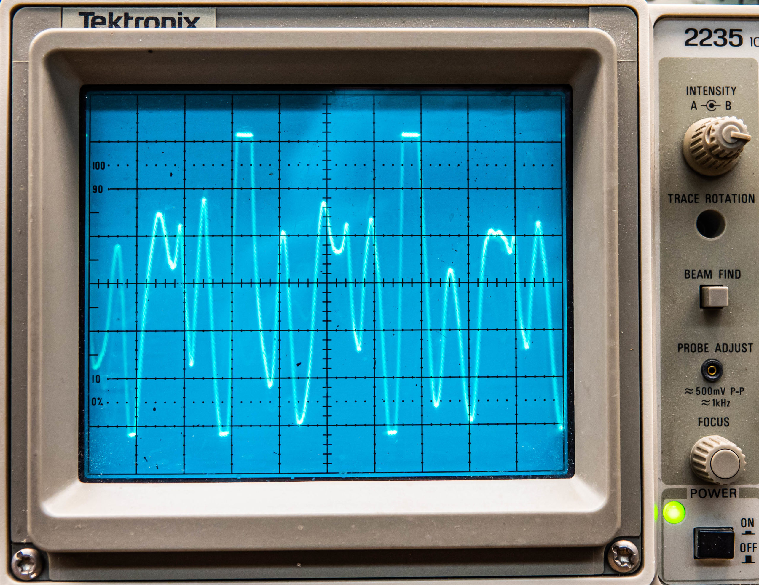
Fig. 1 shows an oscilloscope with voice audio going up and down in voltage. You’ll notice the tops of two of the positive peaks are cut off and there is a smaller amount of clipping on negative peaks. Audio that was intended to go higher in voltage was stopped by the capabilities of the equipment to reproduce it. That means pieces of audio were then missing from the final mix because the audio has exceeded the peak-to-peak voltage capability of the equipment. The sound quality is now degraded.
There is no need for this kind of audio mishandling when the noise floor is so low.
Try it for yourself
Deliberately run audio into the red and beyond on a recording. You’ll hear the mush that it turns into. Valuable audio information is lost, and it just plain sounds bad. Not all hear the beginning of clipping where audio peaks are missing. Female listeners are usually the first to notice problems. They don’t know what it is, but tuneout is the result.
Digital audio has the same problem, where analog audio is converted to digital. Overdriving the input to an analog to digital converter will result in peak distortion.
The opposite can happen, especially during talk shows with multiple microphones. Guests are often soft-spoken. The host or control operator can hear just fine, but listeners, especially in noisy automobiles, have trouble hearing. Car passengers don’t have the benefit of studio headsets cranked up. Road noise tends to mask radio voices. There is another tune-out.
Analog broadcast audio console audio is high enough to hear when you put a headset across the audio output terminals, or anywhere in an audio chain leading up to audio processing. I always carried a traditional telephone handset with alligator clip leads to listen to and find problems in audio paths. Today’s headsets with impedance of 4 to 32 ohms are not as suitable as older high-impedance (600 ohm or more) headsets that do not seriously load and reduce audio on a line they are connected to.
[Sign Up for Radio World’s SmartBrief Newsletter]
Audio power
By definition, 0 dBm is 1 milliwatt. That and +4 dBm (2.5 milliwatt/.0025 watt) is the audio output of most analog audio consoles today.
A small traditional (incandescent lamp) flashlight might consume 1 watt of power. You can see by comparison that audio power is very small in broadcast facilities. The exception is studio monitor speakers that run many watts. Audio from a public address system might have enough power to illuminate a good-sized light bulb.
Broadcast audio level is measured as dBm into a 600-ohm load. This standard goes back to the days when audio was sent from a studio to a transmitter site, via a dedicated telephone line. Referring to my earlier article “Ohms Law Answers Your Questions,” we can figure voltage and current. By knowing two electrical parameters, we can solve for the third.
In this case, 1 mW into a 600-ohm load is 0.775 volts. You won’t measure that with a multimeter because audio varies from zero volts with no audio to something much higher during voice or music. Fortunately, there is metering built into audio consoles and digital recording software. Those meters are calibrated to show when audio levels are correct. Rely on them, not your ears, when adjusting audio. Your ears are a bad judge of how loud or soft audio is.
Impedance matching was a big concern in handling audio until the early 1980s. Gain was expensive to achieve with tube and transistor circuits. Audio transformers were a popular choice for changing impedance and coupling precious audio from one device to another in the broadcast chain. Integrated circuits with operational amplifiers solved the problem by providing gain with high-impedance inputs and low-impedance outputs at a low cost.
Impedance
For the purpose of this discussion, audio impedance can be thought of as mostly resistance. It is what you have in a resistor. Audio impedance can contain some inductive reactance or capacitive reactance, but that is not normally a factor unless it is added intentionally.
Audio transformers might still be found in some legacy installations for coupling audio from one place or device to another. Frequency response can be poor if the transformer doesn’t see a specified load resistance. Low and high frequencies may no longer be at the same level as mid-range 1 kHz and could sound strange. The other problem is that all audio transformers taint the audio a bit. What comes out of a transformer will not be exactly what went in.
Transformers have traditionally been used to solve hum problems in audio. They can ignore ground voltage differences between two devices. This can even happen within a studio between two pieces of equipment.
One place where transformers can go wrong is when connecting one transformer directly to another. The result can be poor frequency response. I remember an unwanted 4 dB bass boost around 150 Hz when that happened. All that was needed was a 3 dB resistor audio pad between them to keep the transformers from “electronically talking” to each other.
Audio transformers can exhibit poor frequency response when not terminated or not terminated properly (Fig. 2). If an audio console has an output transformer, you should take care to make sure it sees the specified load impedance, which is normally 600 ohms. If the device it feeds has an input impedance of 600 ohms, then that is OK. If it is feeding a 10,000-ohm bridging device like a digital recorder, then it needs a little help. Put a 620-ohm or 680-ohm resistor across the output terminals. The total resistance is close enough to 600 to keep the transformer happy. The power is so low that a quarter-watt resistor is fine for the application.
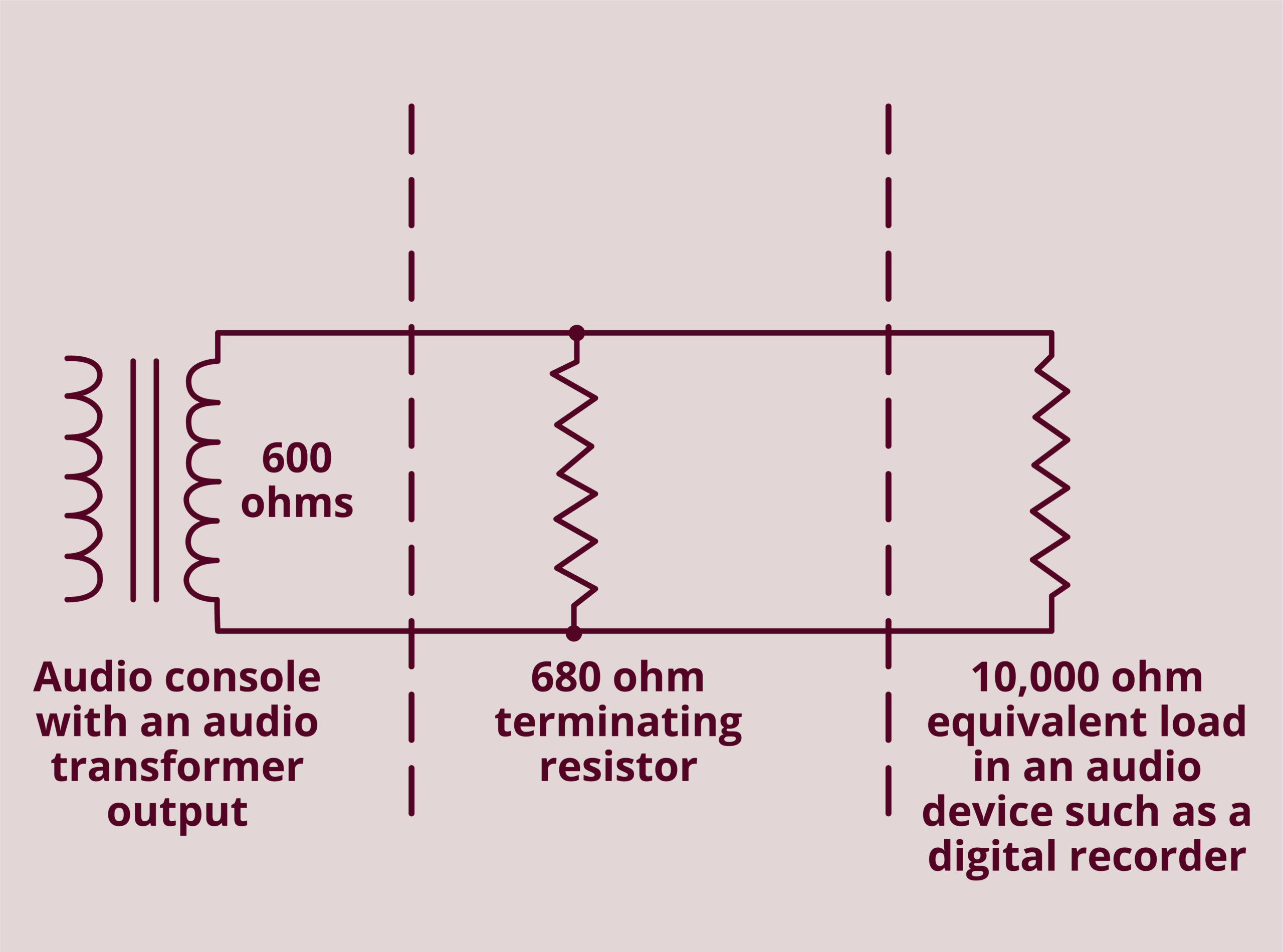
Fig. 3 shows an audio transformer terminated with a half-watt resistor. If you do the math, sixteen 10,000-ohm loads have a combined parallel resistance of 625 ohms. It works.
An analog audio console without transformers might have an output (source) impedance low enough to deliver audio at its output terminals so a 600-ohm load could be placed on it without causing problems. Many consoles today have output impedances as low as 50 ohms. The console doesn’t need to see a termination resistance. Audio can be fed from there to multiple locations if those devices have an input impedance of 10,000 ohms or so. Up to 50,000 ohms is common in today’s equipment. Today’s active balanced audio solves problems without audio transformers.
In conclusion, beware of audio pitfalls. Know and understand audio in the facilities you work on. Radio depends on keeping listeners. My next article will explore more of the science of broadcast audio.
Read Part 2 of Mark Persons’ series on audio fundamentals: “Let’s Connect Audio in a Studio”