The author is a longtime contributor whose articles about engineering and radio history are a popular recurring feature.
Broadcast engineers love to talk. Recently, over a pleasant long lunch, between being handed the menu and the final credit card receipt, the conversation was all about equipment and its manufacturers.
Somewhat surprising was that we cohorts all shared a sort of uniform appraisal of one particular purveyor that has the knack of supplying gear which, no matter how challenging the task, seems to have that highly desirable perfection of elegant simplicity of design.
These folks just seem to be able to choose the ideal circuit solution, select the optimal devices, somehow minimize the parts count as well as achieve exceptional feature flexibility with an intuitive operating ergometric control panel. No wonder the firm has had a longevity of success and a sterling reputation to match.
On the drive home, I pondered my own design work over these last nearly 60 years. What was my design record and how would my own work stand up?
In the rearview mirror review, I seemed to have toggled between mostly the near obscenely overly complex and a small handful of well-realized, durable, slick circuit solutions.
Out of this rumination, one simple yet highly useful device with a Spartan simplicity came to mind that has been optimized on my drawing board over a dozen reincarnations.
An old friend
Most recently, a need has appeared for small translator transmitters to deliver the low-power FM signals assigned to AM stations.
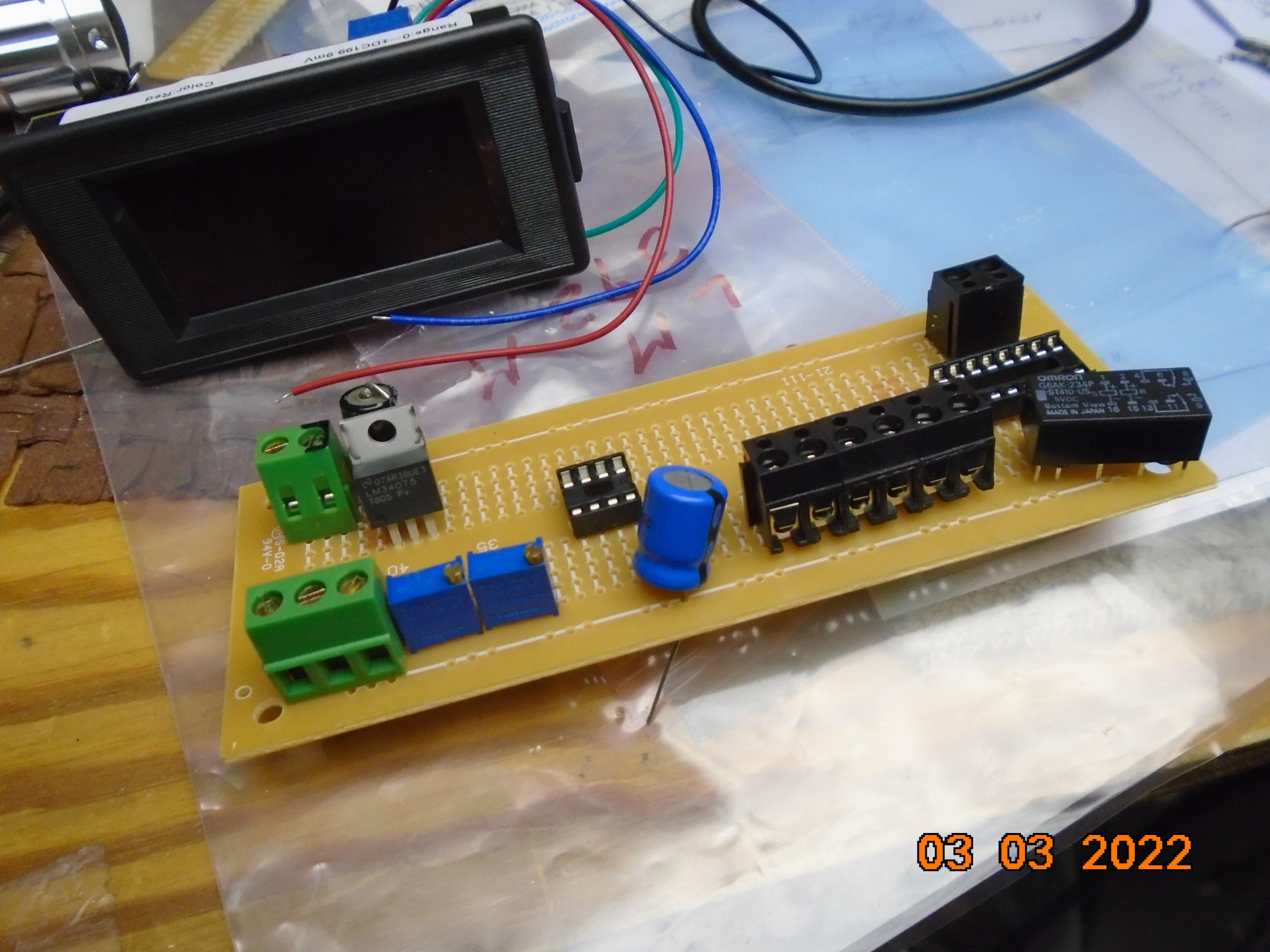
Like many laboring on these projects, I fabricated a purpose-built unit in the 200-watt class, and as on past similar efforts, I found that I needed an accurate operating internal thermometer with digital readout.
To that point of simplicity … the most often-used, cost-effective sensing device for this application is an old friend, the venerable LM-34, which outputs a linear voltage analog of the ambient temperature.
From this starting point of an accurate proportional value, this particular version of my classic design can accomplish many tasks and provide an important measurement.
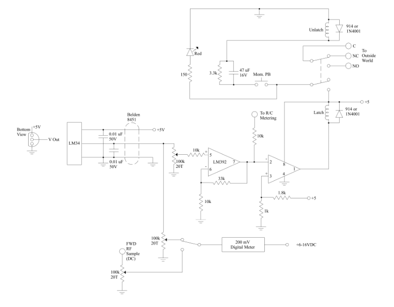
Please review the schematic shown at the top of this article, as it will help you follow along with the circuit explanation. And here is the parts list for this project, in an Excel file.
The LM-34 provides 10 mV of output per degree Fahrenheit from 5° F to 300° F if no offset compensation is used to allow reading temps below 5° F. As such, typical room temperature (72° F) would produce 0.72 volts at the output.
This device comes in three formats but most often looks like a plastic TO-92 transistor. It is quite amazing as it has all the circuitry to generate this analog output as well as an internal regulator, so you can impress any supply voltage from 5 to 20 volts … all inside this tiny device.
(The metal can TO-46 format, pricy and often hard to find in one quantity, is available as a help in horrendous RF environments as the ground/common lead grounds the can.)
Many people use this voltage output directly, but in an RF environment, it’s good engineering practice to amplify the output so that it is above the residual noise level as much as possible. The 0.01 uF ceramic capacitors on the LM-34’s voltage supply input and the analog output to ground are attached as close as possible to the device and are for RF decoupling. The specification of Belden 8451 or equivalent wire shields the signal flow of this low-level data as it travels.
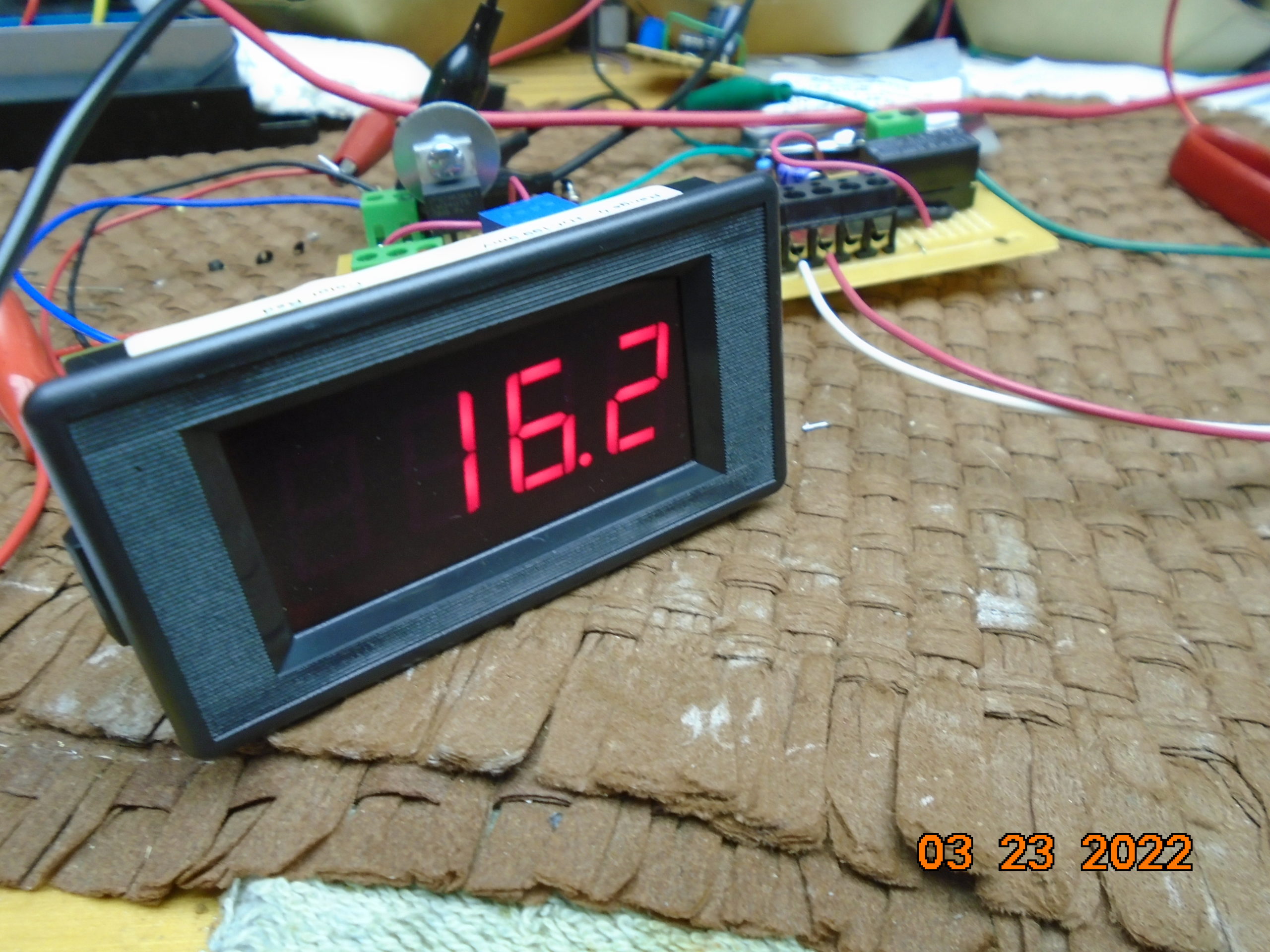
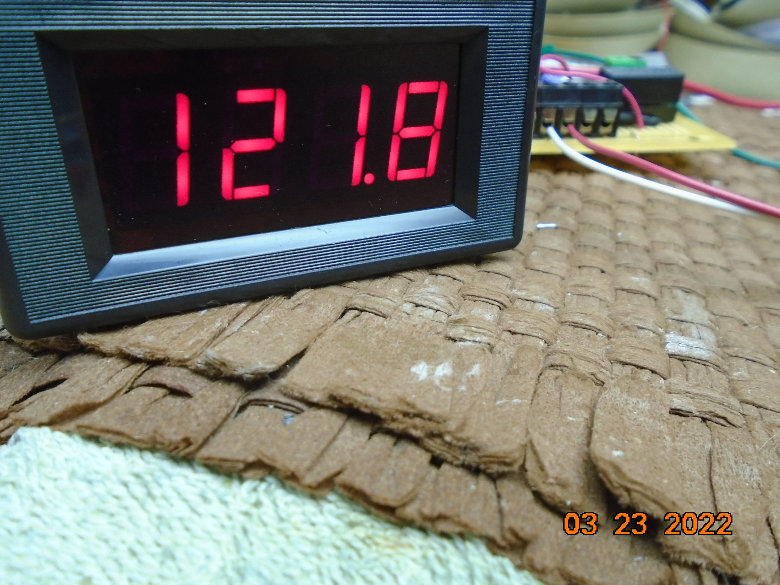
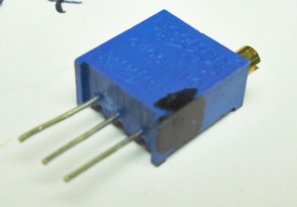
This layout does use the output directly as a selected input for a typical 200 mV front-panel digital meter. The parallel 20-turn 100 kΩ potentiometers are a trifling and stabilizing load at 50 kΩ for the LM-34. The pot, when properly adjusted, allowed a direct temperature display on the meter. Not drawn but a nice touch was for that same switch that selects this metering input choice also properly positions the decimal point on the meter.
[Check out more of Radio World’s Tech Tips]
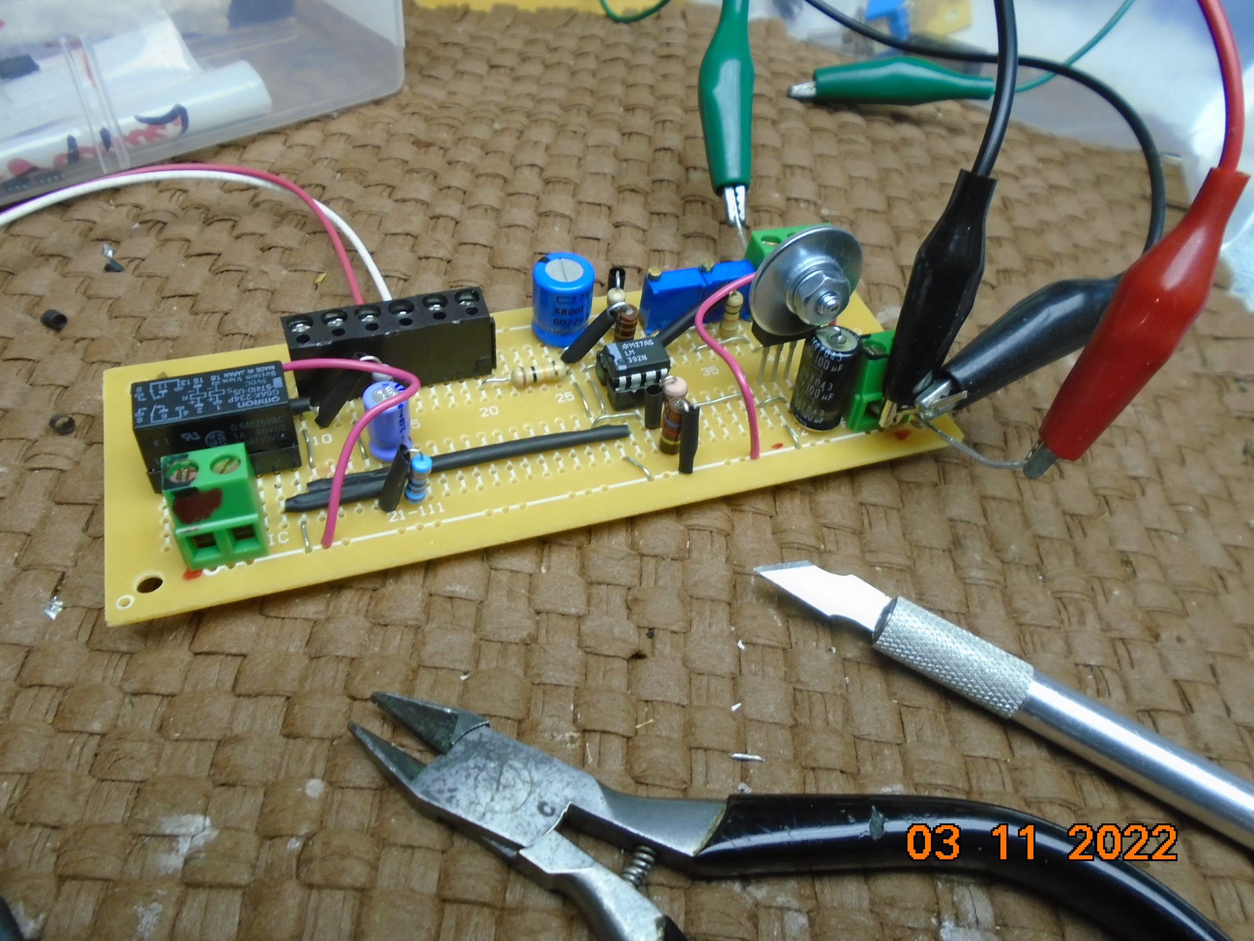
The ubiquitous LM-392, one of the oldest and most useful of the DIP-type linear ICs, conveniently has two distinct sections perfect for this project. The first works well as an op-amp, and the second as a very nice comparator.
We’ll ask this IC to perform both these tasks for us. The former section provide gain for easier signal handling and a more definite decision point, and the latter is used as a comparator to generate a temperature extreme alarm.
In the case of my unattended LPFMs, I used the overtempt, as shown in the schematic, to latch off the RF power amplifier for attention to the problem’s cause at a later time, preventing self-generated damage in the meantime.
The gain of this little op-amp as drawn is a nominal 3, which raises the 72° F (0.72 volts) previously mentioned to about 2.2 volts. You’ll also notice an optional branching resistor from this stage output which allows one to take a healthy voltage sample to a remote control system’s telemetry input, which can be used as an analog value to display the temperature sensed by the LM-34. This resistor is shown as 10 kΩ, but you can lower this value some if your remote control system requires more sink current.
The comparator has a fixed trip point of 3.3 volts, which when finally adjusted I made correspond to 122° F, sort of the universal maximum high temperature to which most broadcast gear is intended to operate properly.
Since the LM-34 conveniently outputs a linear voltage, substituting 1.22 volts in place of the LM-34’s output allows you to set the 122° F trip point by adjusting R1 to activate the trip. The latch relay that I used was a 4.5-volt type intended to work in TTL circuits. The latch coil draws about 16 mA to operate, and that is within the range of the comparator section’s independent output pass transistor’s 40 mA limit. This transistor conducts to IC ground (open collector) when “high,” and hence is in the negative return of the latch coil.
The first insert is a following high-current control for sinking more current if needed. If you need to change voltage levels, such as controlling 24 volts, a 4N33 optical Darlington isolator works really well.
The reset push button is mounted front-panel on my LPFM amp, and this sends a voltage to the high side of the “unlatch” coil through electrolytic capacitor C1, which allows current to flow into the unlatch coil for about one second. The 3.3 kΩ resistor will discharge the capacitor in less than five seconds unless you continue to push the button.
If voltage is present on the latch coil, the relay can’t move. If the temperature has dropped below the trip point, the relay will reset, allowing overtemp operation once again.
As noted, you can customize this circuit in whole or in part for your own applications. You can use the latch feature to latch a status alarm on your remote control. As noted, you can simultaneously grab the op-amp output for a low-noise temperature value for the remote control. You can bring out the reset (unlatch coil) control to your remote control to test if the alarm is ongoing or past. You can eliminate the latch section and thermostatically operate the AC or a fan.
In smart remote control systems, you can even use the overtemp to summon the HVAC repair people on high temperature alarm.
Elegant, simple, flexible, useful. As was said at the end of the original “Outer Limits,” we now turn control over to you.
[Related: “Sometimes It’s Best to Roll Your Own“]
Top Tips
As the Brits say, here are some “top tips” to help your project come together successfully.
- Multi-turn PCB pots as appear in this project, usually in very tiny print, are marked for rotation direction with the related change in resistance value. I find that marking the pot arm that is furthest from the center arm when the pot is fully clockwise (CW) that in most circuits is connected to ground with a black sharpie reduces orientation mistakes.
- Working on small prototype PCBs I have the best results using ultra-thin solder and running my Weller WESD51 soldering station at 567 degrees F. In that series the ETA-1/16 1.6 mm screwdriver tip, for me, matches the DIP spaced solder pads best avoiding solder bridges between sections.
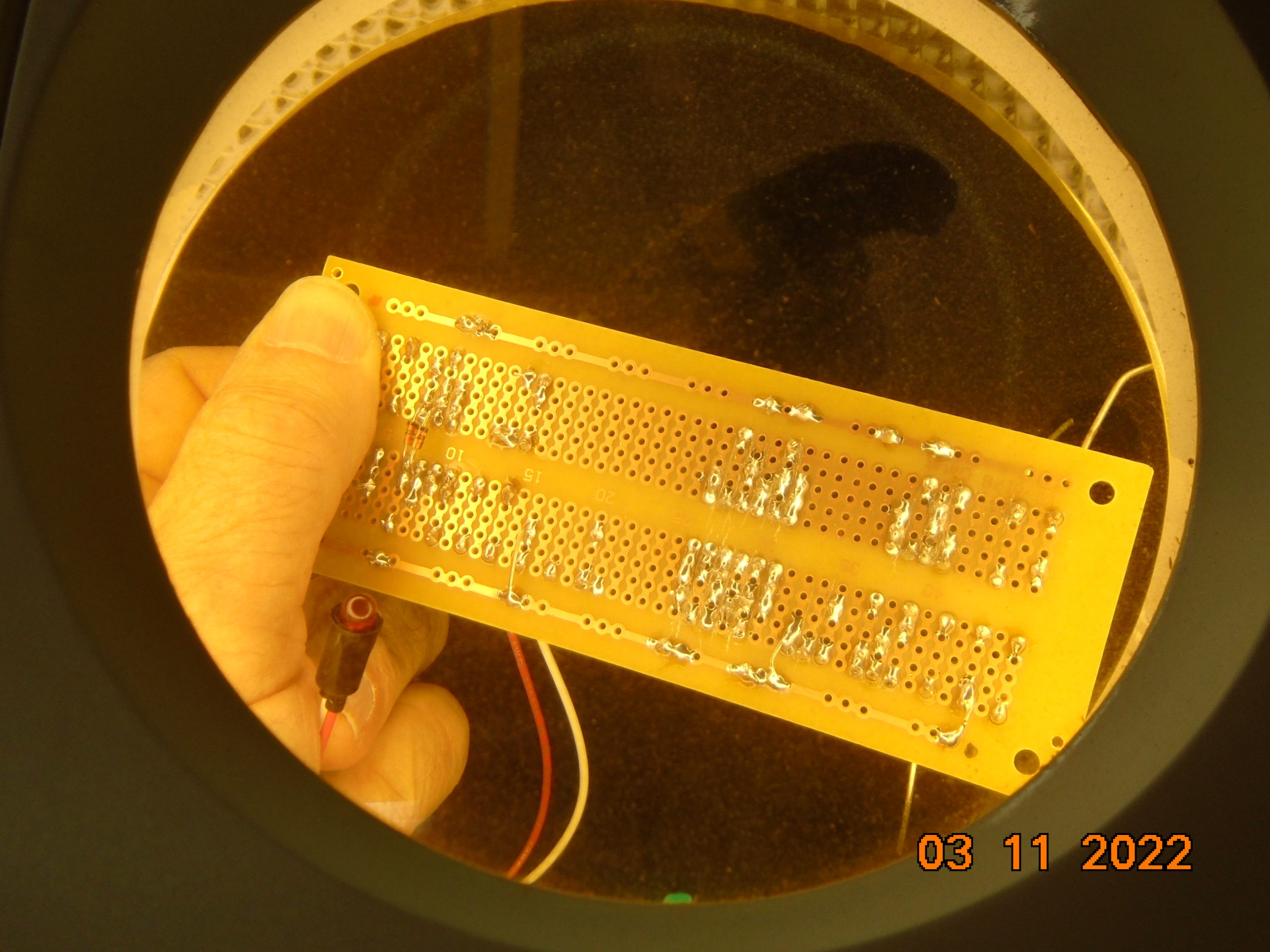
- With prototype PCBs, you achieve your best results if you really plan your layout ahead. Temporarily mount/position your components and then make an accurate drawing to any needed connection pads or wire jumpers. Yes, this is tedious but winging as you go quite often boxes you in such that you have to trash what you’ve done to that point.
- Always inspect your work as you go and especially before any periodic testing. With proto PCB DIP-type construction, look carefully at the solder traces and if possible with either a jeweler’s eye or magniscope. Catching errors at an early stage will save you a lot of grief and troubleshooting time later on.