My career in radio broadcast engineering has been aided tremendously by an understanding of Ohm’s Law, the brick and mortar of electronic engineering. This easy-to-understand knowledge tells the story of how things work and helps immensely in diagnosing a problem. The mystery of “how does it work or what went wrong” often goes away when Ohm’s Law is applied.

Pie chart
The answer is in front of you on the chart in Fig. 1. Solve for voltage (E) in volts, current (I) in amperes, resistance (R) in ohms or power (P) in watts when you know two of the values. You might use this knowledge on a transmitter where meters show volts and current. These aren’t just numbers, they mean something. On a tube transmitter it could be 8000 volts. When multiplied by 3 amperes of current, it equals 24,000 watts input power. Then there might be a 75% power amplifier efficiency to give a power output of 18,000 watts. Look at the original transmitter test sheet to find the factory measured efficiency. Simplify the math by using a calculator or smartphone app.

LED indicators
There are many occasions when a small lamp is needed to indicate status (Fig. 2). It might be a green power light on a piece of equipment or a red light in an off-air alarm. LED pilot lamps have been around for over 50 years, and many in use back then are still functional. Try that with an incandescent lamp!
The most common size is T-1 3/4 or 5 mm, as shown in the photo. They come in red, green, yellow and even blue. You can buy them with dropping resistors for specific voltages, but the most common way of designing a circuit is with a basic LED that has a forward voltage drop of 2 to 3.5 volts DC. Voltage varies depending on size, brightness and color. The schematic symbol of an LED has one or two arrows pointing away, indicating that it produces light.
Think of an LED as a current specific component rather than voltage. By voltage, I mean something like a 120 VAC room light, which is built to consume 40 watts or 100 watts, but still runs on 120 volts. LED indicator lamps make light based on current passing through them. More current means more light output. The voltage across the LED will vary only a bit with brightness.
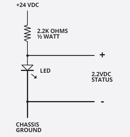
What size series resistor is required for a 2.2-volt LED in a 24-volt DC circuit when we want the lamp to run at a typical 10 m.a. (.01 ampere) of current (Fig. 3)? The resistor must drop 21.8 volts (24 source volts minus 2.2 LED volts). Using Ohm’s Law, we divide the 21.8 volts by the .01 ampere, and we get 2180 ohms. The nearest standard resistor value is 2200 ohms. Close enough. And as indicated on the schematic, you can sample voltage across the LED as a status input on a remote control. This assumes the remote metering input impedance is 10K ohms or more so as not to seriously upset the circuit voltage and resistance values we just discussed.

Use Fig. 4 if you need 4.4 volts for status, use two LED lamps in series and adjust the voltage dropping resistor accordingly. In the case of 24 VDC power supply, subtract 4.4 volts from 24 to get 19.6 volts, then divide by the LED current of .01 ampere to get the resistor size of 1960 ohms, although 2000 ohms is close enough.
Heat
A resistor will get warm in doing its job. Using Ohms’s law, voltage times the current will tell us watts. In this case, 21.8 volts times .01 amperes = 0.218 watts. Resistors are rated at the number of watts of heat they can safely dissipate before failure. Of course, you don’t ask a resistor to dissipate its maximum rated power. I like to double the resistor wattage size to allow it to run cooler and have a long service life.
Resistors need ventilation. The heat needs to go somewhere. Give them breathing room. Run the circuit for a while, then shut off the power and feel how warm the resistor is. If it is too hot to touch, then the resistor is not the right size for the circuit.
There are blinking LEDs too where all the electronics to make them go on and off is inside the lamp. Those are handy eye-catchers for situations where human intervention is required. You can run LED indicator lamps on alternating current if you don’t exceed the maximum allowed reverse voltage, as specified by the lamp manufacturer.
120-volt power
There you are, out on remote with a 1500-watt electric space heater. Using Ohm’s Law, 1500 watts divided by 120 volts gives us 12.5 amperes of current. The heater’s resistance is 120 volts divided by 12.5 amperes for 9.6 ohms. But then you add an extension cord to the mix. It might be made of 16-gauge wire and probably came with a tag indicating it is capable of 13 amperes. All should be good, but let’s do further analysis. Looking it up, that #16 copper wire has a resistance of 13.2 ohms per thousand feet. The inexpensive 50-foot extension cord has 100 feet of #16 when you consider the power goes to and from the heater. That is 1.32 ohms of wire loss.
Adding the 9.6-ohm heater to the 1.32-ohm extension cord, we come up a 10.92-ohm circuit. Solving for current, Ohm’s Law tells us there will be 120 volts divided by 10.92 ohms for 10.99 amperes when we were expecting 12.5. That is extension cord loss. The voltage at the heater will be lower. Using Ohm’s Law, 10.99 amperes times 9.6 ohms equals 105.5 volts at the heater. That means 14.5 volts were lost in the cord. If we take 14.5 volts and multiply it by 10.99 amperes, we get an astounding 159 watts lost in the extension cord. Check the cord, it is probably getting warm! That is 3.18 watts of heat per foot. Not unexpected, but it could be a serious problem if the cord is coiled in a non-ventilated area.
The cord is plugged into a 20-ampere outlet. Let’s say the electric heater is rated at 2400 watts and is on the #16 power extension cord. As per the math before, the heater resistance is 6 ohms. Added to the cord’s 1.32 ohms, and that is 7.32 ohms in the 120-volt circuit. The current will be 120 volts divided by 7.32 ohms for 16.39 amperes in the 13-amp cord. Solving for power lost in the cord, multiply the 16.39 amperes by itself and then multiply by the 1.32-ohm resistance to get 345.6 watts. Now we are talking 7.09 watts of heat per foot in the cord. That is too much! It will work until the cord starts smoking and maybe catches fire.
Of course, there are connector losses too. Some 120 VAC plugs and receptacles are rated for 15 amperes and others are for 20 amperes. Choose wisely.
12-volt power
This is where wire size becomes more important. Amateur radio operators know it well with much of their equipment powered by batteries. It takes 10 times the current in amperes to deliver 100 watts at 12 volts than it does at 120 volts. That 100 watts might be for a remote broadcast transmitter and an inverter to power a computer and lights etc. Yes, there are still some Marti remote broadcast transmitters in use today. Solving for current in amperes by using Ohm’s Law, take 100 watts and divide by a typical 12.6 battery voltage and you get 7.94 amperes. The resistance of the equipment is 12.6 volts divided by 7.94 amperes for 1.59 ohms.
The previously mentioned 16-gauge wire is rated at 13 amperes, but how will it work in this situation? The 13.2 ohms per thousand feet is 0.66 ohms over a 25-foot cable when you figure the two conductors total 50 feet in length. With that in mind, how much voltage will be available for the equipment? Add the 1.59 ohms of equipment to 0.66 ohms of battery cable and you get 2.25 ohms.
OK, but what does that mean? Solving for current, it is 12.6 volts divided by 2.25 ohms for 5.6 amperes. What happened to the other 2.34 amperes? The power cable ate it. Ouch! The equipment gets only 8.9 volts when you multiply the 5.6 amperes by the load resistance of 1.59 ohms. The cord gets 3.7 volts times 5.6 amperes resulting in 20.72 watts of heat.
A better choice is #12 wire where its resistance is .08 ohms over 50 feet. Add that to the equipment load resistance of 1.59 ohms and you get a total circuit resistance of 1.67 ohms. At that point, the total circuit current will be 12.6 volts divided by 1.67 ohms for 7.54 amperes. Solve for voltage at the equipment by multiplying the 7.54 amperes by the equipment resistance of 1.59 to get 11.99 volts. That works.
You will notice the equipment got 0.61 volts less than desired, but that is reality in battery powered situations. Worse yet, the 12.6-volt battery will settle down to 12 volts after a while of operation, making it more difficult to keep equipment running. That is all the more reason to use larger gauge cable to keep cable loss to a minimum.
As you know, stranded cable is easier to handle in remote broadcast situations. It has the same amount of copper for a given wire gauge number, but flexibility makes stranded the best choice for everyday use and long-term reliability.
To conclude: Ohm’s Law helps engineers understand engineering problems and create solutions. Be prepared to think through electronic engineering problems. A working knowledge of Ohm’s Law is a good basic starting point. Without it, you might miss the answer to the problem presented.
Comment on this or any article. Write to [email protected].