Readers of my articles featuring DIY projects may be interested in trying their hand at creating a device from scratch. A great place to start is with a clear, well-drawn schematic.
For the last several years, I’ve relied on ExpressPCB for creating the necessary diagrams and circuit board layouts for my projects. As with any DIY application such as this, there are numerous such tools available, and most will do nicely. It mostly comes down to personal preference and workflow.
I asked some of my buddies at www.groupdiy.com for their recommendations and I got several, a few of which I’ll discuss along with one or two I found on my own.
This is by no means a comprehensive list and is not intended to be a review. It’s a sampling of recommended tools available.
Preliminaries
A couple guys I chatted with still rely on a hardware-based solution, otherwise known as good old-fashioned pencil and paper.
There’s a lot to be said for that. The learning curve is determined only by one’s knowledge of electronics, which is a given at this stage. There’s nothing to download, no parts library to maintain, and custom or oddball components are easily created.
The downside is that all but minor changes in the schematic can require starting over, or trying to read through a mess of eraser smudges. And in my experience, the only professionals with handwriting as bad as doctors are engineers!
Using software to create schematics may take a little longer, but the effort often streamlines the completion of the project. The programs I tried all come with PCB creation tools that allow finished schematics to be ported in from their own or third-party software. They also allow for designs to be exported for manufacturing purposes, if the project moves beyond the DIY stage.
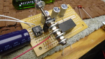
In order to test the various programs, I took a design for a simple bipolar power supply I’ve used in several builds, and I tried to recreate both the schematic and the PCB in each program.
Since it was originally created using ExpressPCB I’ll start there.
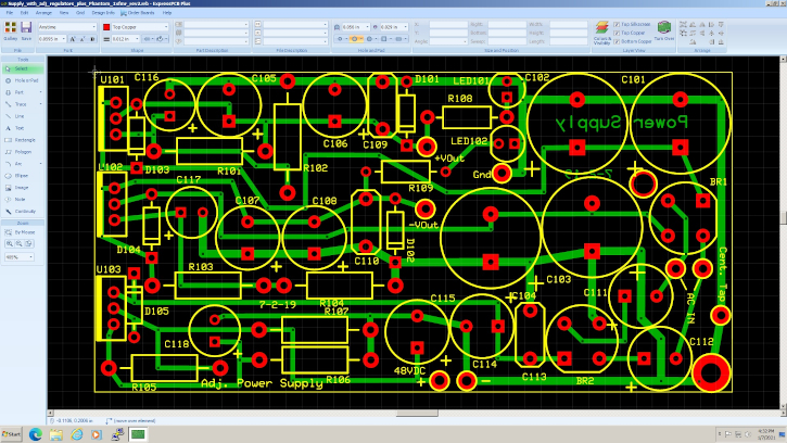
ExpressPCB
The free download of ExpressPCB (www.expresspcb.com) installs two separate programs on your PC. (There are no Mac or Linux versions as of this writing.)
ExpressSCH handles the creation of schematics. It includes a library of commonly used parts, and users can also create custom components. ExpressPCB can import those schematics, or users can work from scratch. Again, custom components can be created.
The classic version of the software can accommodate PCBs up to four layers, while the “plus” version can handle six. The “plus” version also has a larger library, can copy and paste between designs, and can provide silkscreen patterns for both top and bottom layers.
The interface is pretty intuitive, but the online documentation will walk users through the more complicated features.
ExpressPCB offers a manufacturing service for completed designs, but it’s also easy to print what’s needed for etching boards at home.
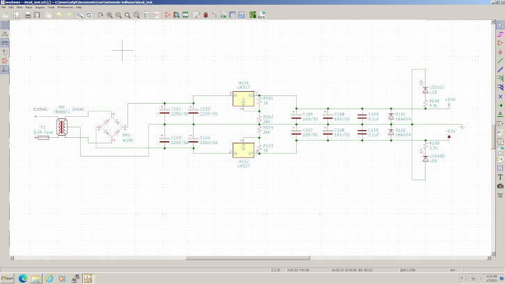
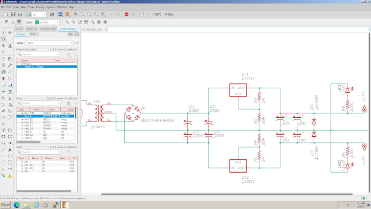
KiCad
Next up is KiCad, available as a free download from www.kicad.org. KiCad is open source and available for PC, Mac or Linux.
The schematic program, called Eeschema, includes a large parts library, plus the ability to match schematic symbols with specific PCB footprints. This facilitates PCB design by automatically including the correct footprint for each component, and aiding in trace layout. It also includes design rules checks to keep mistakes to a minimum, and a circuit simulator to test designs.
Another interesting feature is the 3D Viewer, which allows users to envision how a populated board will look, a big help with figuring out how much space the project will take up inside the chassis.
KiCad also exports Gerber files and provides printouts for home etching.
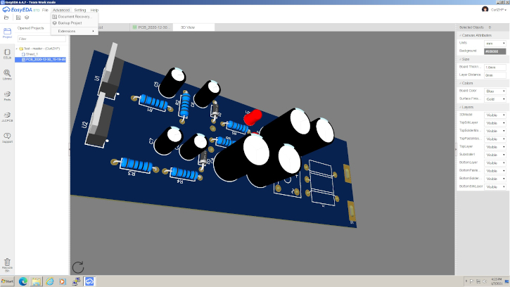
EasyEDA
EasyEDA (www.easyeda.com) also is available for PC, Mac and Linux. It comes in two versions: the Desktop Client and the Online Editor.
The Online Editor allows users to work on designs from anywhere they have internet. Both versions also allow for team collaboration.
The program includes links to a user forum as well as tutorial videos for help with designs. Like KiCad it also has a 3D viewer, design rules checks and Gerber export capability, as well as a large parts library with matching component footprints for PCB work. Multiple PCB layers are supported.
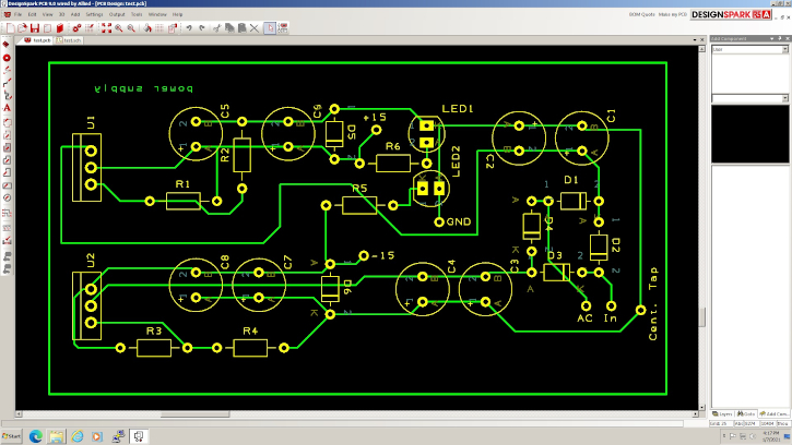
DesignSpark
DesignSpark comes from a partnership between RS Components and Allied Electronics. The software requires free registration at www.rs-online.com/designspark/home. The site offers a vast library of tutorials, projects and other information for DIY.
The schematic software includes a good-sized parts list, and like KiCad and EasyEDA it includes footprints for common components. Like the others, it includes a 3D viewer, design rules checks and Gerber output, as well as multilayer board support.
DesignSpark also includes a Design Calculator tab, which includes not only a scientific calculator but also calculators for trace width and impedance, RCL frequencies, heat sink values and common conversions. On the schematic side, it includes a Spice simulator.
Eagle
Finally there’s Eagle by Autodesk (eagle.autodesk.com). This free download includes almost all the same features as KiCad, EasyEDA and DesignSpark.
Schematics can be created from a vast library of components that include footprints for automatically porting into the PCB side of things. Dozens of possible layers are supported, as well as error correction and virtual test probes.
Another handy feature is the ability to create what are referred to as “design blocks.” These are essentially electronic sub-assemblies that can be saved as standalone components. For example, if several designs use the same power supply or output stage, that section can be saved as a block, rather than having to redraw it every time.
There is one drawback to this program: the free version limits the size of PCBs to 100 x 80 mm.
Again this is by no means an exhaustive list of available programs. All of these will certainly get the job done. Some have a much steeper learning curve than others, mostly due to the sheer number of features and options.
It really comes down to each DIYer’s preferences and workflow. I’ll likely stick with ExpressPCB, simply because I’m used to it.
There were some nifty features in the others but none that I couldn’t live without. I especially liked the 3D viewers, and while it took a while to find the right parts, having specific footprints for specific parts took a lot of the trial and error out of fitting everything on to the board. On the other hand, most of my projects are not as complex as the majority of these programs are designed to deal with.
If you’re looking to take your schematics to the next level, it costs nothing but time to try any of these solutions.
Do you have a program you prefer? Tell us about it at [email protected].
Curt Yengst, CSRE, is engineer for Lighthouse TV in Allentown, Pa.