In this final installment of a series of articles aimed at helping broadcasters protect their installations from powerline and lightning-induced surges, we focus on the importance of electrical bonding and a properly installed grounding system.
When you think about it, bonding and grounding are sort of “joined at the hip,” as when you ground gear you’re really bonding it to the Earth’s potential. As Kevin Turner, an AC power specialist with Smiths Power, put it, “Surge protection, grounding and bonding are like a three-legged milking stool. You remove one of the legs and things are not going to work properly.”
We’ve been championing the use of “surge suppressors” to protect broadcast facilities, but these can’t be viewed as the “end-all and be-all” in terms of equipment protection. In discussing lightning protection, Jeff Welton, Nautel’s regional sales manager for the central United States and former customer support technician for the company, stressed the importance of proper grounding in helping to ameliorate the effects of lightning strikes to towers.
He cited the case of one customer who was experiencing repeated transmitter power supply failures and assumed that the problem was due to AC line surges.

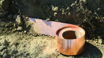
Broadcast facility grounds need to be either brazed/soldered with “Sil-Fos” alloy or “CAD” welded to achieve a long-lasting, low-resistance connection. (photo credit: Nautel)
“They had installed a surge protector and thought they had the grounding done perfectly,” Welton said. “We came in and one of the first things we noticed was that there was no ground rod at the base of the tower. We installed one and connected their surge protector to a proper ground at the AC entrance [and then] connected this to the tower ground with copper strap. The ‘ground rod’ to which they’d tied the surge protector turned out to be a piece of rebar from the concrete building pad, not a ground rod at all. Their power supply failure rate went from several per month to one in five years. These failures were being caused by transients coming in on the RF transmission line, not the AC line. The surge box was there, but without a good ground connection, there was no place for the energy to go — the only place it could go to dissipate was to the AC lines through the transmitter power supplies.”
In addressing grounding, Welton emphasized several points:
• “Lightning” grounds should be as physically short as possible to minimize inductance. Also the use of a conductor with the largest surface area possible is good engineering practice, as lightning contains high frequency components and the conductor “skin effect” can come into play. A two-inch copper strap has a greater surface area than a 2/0 cable.
• Ground connections should be either brazed or soldered with “Sil-Fos” (trade name for a silver-copper-phosphorus alloy), or “CAD” (thermite) welded. Clamped grounds will slowly show an increase in resistance as conductors oxidize over time.
• All coax shields need to be grounded where they enter the building and connected to a single point to avoid ground loops. This can be done in a “tree” configuration in a multi-room situation — studio and/or shared transmitter site — with each room having a common ground point and each piece of equipment individually grounded to this point. Each of the common points is then connected to main facility ground.
Greg Best, a Midwest telecommunications consultant and owner of Greg Best Consulting, offers some additional grounding pointers.
“What you need to do is to eliminate any current flowing inside the transmitter shack by employing proper grounding techniques,” said Best. “Grounding to meet or exceed Motorola’s R56 standard is very important. For rocky or poor soil conductivity areas, you might want to use a ground-enhancing material such as Lyncole’s GEM (ground enhancing material) when you’re installing a ground system. It really helps improve the conductivity and can lower the resistance of the ground system.”
LIVING WITH GROUND LOOPS
It’s best to avoid ground loops if at all possible, but in some situations they are unavoidable. Nautel’s Welton suggests some “workarounds” in such cases.
“A transmitter will have [metallic] electrical conduit running to it, as well as an AC safety ground and a coax shield,” Welton said. “This [situation] can be optimized in several ways, such as by using non-conductive conduit nipples to eliminate the conduit as a ground connection and by keeping wiring between the transmitter and the [signal] source as long as possible to maximize inductance.”

If you’ve inherited a legacy broadcast facility, an early order of business is to check plant ground connections. This (very high impedance) “ground connection” to a PVC water pipe actually existed at one facility visited by a transmitter company field engineer. (photo credit: Nautel)
THOSE FERRITE RINGS AGAIN
In a previous installment in this series, Welton commented on the value of installing ferrite rings on transmission lines. He notes that they can be valuable in another way too:
“They help identify ground loops where feed and return currents are not equal,” he said. “They get warmer than the ambient temperature of the room [when such ground loops exist] — and the hotter they are, the worse the ground loop.”
BONDING IS IMPORTANT FOR BOTH EQUIPMENT AND EMPLOYEES
Electrical bonding is basically defined as the tying together of all conductive items in a facility so as to keep them at the same electrical potential. This needs to be done not only for safety reasons — you don’t want operators to receive a shock, or worse, when they touch a rack and coax shield at the same time — but also to ensure the health of expensive broadcast gear and to help eliminate difficult to trace problems with low level signals.
There are other reasons too, one being the minimization of power line “hum” in video or audio. Fortunately, in this age of digital A/V signals and the widespread availability and use of fiber optic technology, this isn’t really the problem it was in analog days. However, just because you are running digital video or audio throughout your plant, you shouldn’t ignore bonding. And Mark Schaefer, director of engineering at Tampa’s WFLA(TV), recalled an incident where potential difference between facilities was anything but insignificant.
“When we built our new transmitter facility it was about 800 feet from the old facility, and as we had a number of satellite dishes at the old site, we had this bright idea to install some underground conduit and run cables between the two buildings,” said Schaefer. “As soon as we had our first lighting storm it blew the hell out of everything. There was enough potential difference between the two locations that when we unhooked cables and lightning would strike anywhere in the area you’d have arcs from the coax cable to ground.”

This large (100 KVA) uninterruptable power supply allows a broadcast facility to coast through commercial power interruptions and can also protect sensitive equipment from powerline “bumps.”
DON’T FORGET POWER CONDITIONING
Along with surge suppression and proper grounding and bonding, conditioning of utility company AC power is becoming increasingly more important in today’s broadcast facility. This is due in large part to the use of switching-type power supplies in computers and other equipment. While such supplies don’t affect the device they’re powering, they can put “trash” back into the mains and in doing so play hob with other gear.
One of the earliest ways to deal with such problems, in the pre-solid-state days anyway, was the use of a large motor/generator — sometimes equipped a flywheel — to completely isolate sensitive equipment from power line “crud.” Fortunately, the development of reliable high-power semiconductor devices have relegated such mechanical approaches to the history books. The “uninterruptable power supply” (UPS) systems of today do a lot more than isolate equipment from mains power; just as the name implies they can make a power failure completely transparent, providing a steady flow of electricity until utility company power is restored or a backup generator is up to speed and ready to take the load. Such a system should be part of any new broadcast facility design or plant upgrade, but if you don’t have the budget for a “whole house” UPS you really should consider installing small “distributed” UPS power conditioning for mission-critical equipment.
Surge suppression, along with proper grounding and bonding techniques, will go a long way in helping you to stay on the air; however, the addition of power conditioning technology completes the picture and adds another layer of “bullet-proofing” to a broadcast facility, not to mention providing peace of mind during storms and man-made power interruptions
James E. O’Neal is a retired broadcast engineer with more than 35 years of experience in the field. For the past 10 years he has served as technology editor at TV Technology magazine.