This paper examines the results of elevated HD Radio carrier power tests performed by Charles River Broadcasting with the assistance of iBiquity Corp. This information was filed with the FCC by Charles River Broadcasting and iBiquity on July 6. The testing program explored the performance of elevated HD Radio carrier power in comparison to the currently authorized –20 dBc carrier power for both mobile and indoor reception conditions.
MOBILE RECEPTION TESTS BACKGROUND AND OBSERVATIONS
(click thumbnail)
Fig. 1: FM Hybrid IBOC Spectral Test mask @ –10 dBc On Dec. 4, 2008 Charles River Broadcasting Co., licensee of WKLB(FM) Waltham, Mass., and a subsidiary of Greater Media Inc., was granted experimental authority by the FCC (file number 20081031ACO) to operate with digital carrier levels up to and including –10 dBc.
This permitted WKLB to operate with digital power levels up to and including 10 dB above that currently permitted by the commission’s rules.
WKLB has operated at various elevated digital power levels during the duration of the experimental authority and recently filed an interim report with the commission, coincident with its request for an extension of such authority, detailing its observations during this period. It was noted in the interim report that WKLB would shortly be conducting additional testing to better quantify the actual improvements occasioned by operation at the elevated digital power levels.
During the past month, Charles River, with the assistance and cooperation of iBiquity Digital, the developer of the HD Radio system, has conducted extensive field testing in an effort to quantify improvements in the WKLB digital service occasioned by increasing power to several discrete levels. Although a number of studies have been previously submitted detailing coverage improvement over a specific route or routes, it is believed that this is the first to comprehensively quantify such improvements over an entire metropolitan area.
(click thumbnail)
Fig. 2: Typical FM Hybrid IBOC Spectrum @ –10 dBc Four heavily traveled radials routes (I-90, I-93, I-95 and State Route 3) and a circular “beltway” (I-495) that encircles much of the Boston metropolitan area were chosen to gain knowledge of digital signal improvements over the entire market. The mobile test platform employed was identical in equipment and configuration to that used for the initial NRSC testing in 2002 and for the more recent testing conducted on Greater Media stations WRAT, WJRZ, WDHA and WCSX as well as several other non-Greater Media owned facilities. Results of these tests have been previously submitted to the commission over the course of the digital radio proceeding.
A JVC Model KDHDR50 receiver was used to determine whether digital reception was possible at any point on a route. This receiver was previously characterized as being “typical” and meeting its published performance specification by iBiquity. Data as to time, location, spectral content and reception mode (analog or digital) was recorded on a micro computer using a proprietary iBiquity data collection program. The receiving antenna was a conventional 31-inch whip mounted in the center of the test vehicle roof (see Fig. 4).


Fig. 3: Dual-Input Antenna

Fig. 4: Mobile Test Platform
All data on each route, for each power level was recorded with the test vehicle proceeding in the same direction. The data collected represents several thousand miles of vehicle operation.
Test Description
For these tests, the system operated in the hybrid mode, which contains the analog FM signal and service mode MP3 digital carriers.
(click thumbnail)
Fig. 5: WKLB @ –20 dBc (–19.21 dBc in Mode MP3) Fig. 1 shows the digital carriers at 10 dB below analog power levels with both the FCC and iBiquity masks. The digital sidebands will exceed the current iBiquity mask by about 8.5 dB. The digital sidebands comply with the FCC mask.
Fig. 2 shows the RF spectrum from the forward sample port of a dual-input transmitting antenna, and the iBiquity spurious noise and emissions mask. As shown in Fig. 1, the sideband power exceeds the current iBiquity digital mask in the frequency range of ±129 to ±199 kHz. Even at the –10 dB power level, the IBOC transmitter is capable of meeting or exceeding the iBiquity mask thresholds established for the –20 dB power level.
Transmitter Test Site
These tests were conducted using the RF transmission facilities of WKLB, Waltham, Mass. (Boston). WKLB was granted experimental authority under 47CFR 73.1510(d) to operate with digital power levels up to and including 10 dB above currently authorized levels.
Please note that WKLB’s total integrated digital power is increased by 0.79 dB over the reference –20 / –14 / –10 dBc levels to accommodate the additional carriers present in transmission Mode MP3.
Transmission Facility Information FCC Facility ID: 10542
North Latitude 42° 18’ 37”
West Longitude 71° 14’ 14”
High-Power IBOC authority per 47CFR 73.1510(d) granted 12/4/08
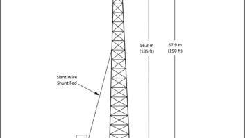
Radiation Parameters AGL 290 m
G AMSL 30 m
RC AMSL 320 m
HAAT 272.27 m
ERP (Analog) 14.0 kW
ERP (Digital) 167.91 W (–19.21 dBc D/A Ratio – Mode MP3)
ERP (Digital) 670.17 W (–13.21 dBc D/A Ratio – Mode MP3)
ERP (Digital) 1679.1 W (–9.21 dBc D/A Ratio – Mode MP3)
Antenna ERI Model 1183-4CP-2 Dual-Input Hybrid IBOC (see Fig. 3) Operating Power
For these tests, WKLB chose to operate each transmitting facility at various total power levels from 20 dB to 10 dB below that of the reference analog carrier. The digital to analog power ratio was verified using digital power meters and transmission system loss/antenna gain calculations supplied by the equipment manufacturers.
Mobile Reception Test Results
Referencing Fig. 5, it can be plainly seen that at the currently authorized –20 dBc power level there are significant and serious digital coverage deficiencies within the WKLB 54 dBu protected analog contour on all routes measured.
It should be emphasized that the “cliff edge” propagation characteristics of digital signals, and specifically IBOC digital radio signals, make any loss of the digital signal, even momentary, extremely irritating to the listener. The effect is not one to which a listener is accustomed, such as multipath or picket fencing, where the audio is still available, albeit compromised. A listener to an HD-1 channel will sense a fall back to the underlying analog signal, which is likely blended to mono and/or experiencing high-frequency roll-off resultant from circuitry included in virtually every analog auto radio, resulting in the loss of stereo perspective and a significant decrease in fidelity.
The situation with HD-2 and HD-3 channels is worse; the signal is simply gone. More than an extremely occasional instance of any such impairment will cause listeners to seek another audio entertainment option.
(click thumbnail)
Fig. 6: WKLB @ –14 dBc (–13.21 dBc in Mode MP3) A close examination of each route will show multiple and numerous instances of intermittent loss of digital service, even prior to those areas where digital service is largely absent.
Fig. 6, representing service at –14 dBc (6 dB above the currently authorized digital power level), shows significant improvement on all routes but also shows evidence of occasional losses of the digital signal within the underlying analog 54 dBu protected contour, again even prior to those remaining areas where the digital signal is more seriously compromised.
Attention is directed to I-93 (between I-495 and the 54 dBu contour), I-495 (from I-93 to the 54 dBu contour) and even I-90 (immediately west of I-495). All these areas exhibit multiple momentary digital signal dropouts, well within the analog coverage area of WKLB. Clearly, operation at –14 dBc provides significant improvement, but fails in terms of replication of analog signal coverage, an absolute requirement if digital radio is to be the successor to that service and the key to listener satisfaction and acceptance.
(click thumbnail)
Fig. 7: WKLB @ –10 dBc (-9.21 dBc in Mode MP3) Fig. 7, representing service at –10 dBc (10 dB above the currently authorized digital power level), shows marked improvement in digital service, as compared to Fig. 2. Other than terrain shadowed area in the Providence/Pawtucket and Plymouth areas, digital reception is virtually flawless over the various routes.
It is extremely important to observe, other than those areas just noted, there are virtually no areas where any momentary digital signal drop outs are evident. This is the level of service a listener anticipates and expects. This is the level of service necessary to ensure the continuing successful roll out of digital radio.
Mobile Reception Conclusions
Clearly, digital radio service at the currently authorized power of level of –20 dBc does not come close to providing the robustness and quality of service anticipated and expected by listeners, based on an analog reference point. This first-of-its-kind survey of an entire metropolitan area proves that fact beyond any reasonable doubt.
Station operation at –14 dBc, a four times digital power increase, substantially improves digital coverage but still does not provide either flawless digital service nor replication of the underlying analog service area, two very basic and critical listener expectations.
Station operation at a –10 dBc level, as proposed by the joint parties, does result in largely impairment-free coverage and replication of analog service. It is critical to understand that the failure mode of a multicast digital radio signal is dramatic and unfamiliar to a listener, representing a total loss of service. Such irritants must be absolutely minimized if listener expectations are to be met.
These maps show significant shortfall in coverage for the important suburban Boston communities of Lowell, Andover, Lawrence and Haverhill, Mass. to the north and Plymouth, Mass., Pawtucket and Providence, R.I., to the south. In addition, numerous areas of the heavily traveled Rt. 495 “beltway” experience severe dropouts of the HD Radio signal. It is apparent that WKLB cannot deliver commuters acceptable digital service at a power level of –20 dBc.
Increasing the digital power by 6 dB (to –14 dBc) dramatically improves the HD Radio listener’s experience on heavily traveled Rt. 495. Beltway commuters north of Lowell and south of Attleboro can now receive WKLB’s multicast programming without interruption. Coverage in Pawtucket and Providence improves, but dropouts of multicast reception here will cause listener tune out. Vacationers stuck in Cape Cod weekend traffic on Rt. 3 will likewise lose the WKLB multicast signal.
A full 10 dB digital power increase (to –10 dBc) appears to be the solution to most WKLB mobile reception issues. The only areas still compromised are low spots in Plymouth, Pawtucket and Providence.
FM HD RADIO SYSTEM PERFORMANCE IN BUILDING INTERIORS AT ELEVATED DIGITAL CARRIER LEVELS
Although at least one previous study (conducted by CBS Radio) has been completed pertaining to the relative ability of digital signals — at various power levels — to achieve penetration of structures, it is believed that the instant report adds appreciably to that body of knowledge and expands the universe of receivers to include the newly released Insignia NS-HD01 battery-operated portable HD Radio Receiver.
(click thumbnail)
Map 1: Site Map for Building Interior Reception Tests Observations were made in a number of varied structures representative of the majority of those in the Greater Boston area and, indeed, the entire United States. Six different locations were selected to be representative of the most common types of building construction.
Location 1, the Greater Media studio building in the Dorchester section of Boston, is representative of low-rise (two-story) masonry, steel and glass construction. Location 2, The Caning Shop in the Cambridge section of Boston, is a single-story structure (with an occupied lower level) of wood and masonry construction. Location 3, the Prudential Tower, in the Back Bay section of Boston, is a high-rise skyscraper of steel, aluminum and glass construction. These locations (1–3) are all located within the urban core of Boston, within 8–10 miles of the WKLB transmission facility in Needham, Mass. (see Map 1).
Even though none are farther than 10 miles from the WKLB transmitter site, they all potentially can suffer from the “urban reception dilemma.” Since many commercial buildings are metallic construction, shadowing, reflection and parasitic re-radiation of the HD Radio signal can cause it to fail. Excessive urban electrical noise only augments the problem.
Location 4 is a typical two-story, split-level residence in Andover, Mass., of wood frame construction. Location 5, the headquarters of the Comrex Corp. in Devens, Mass., is a two-story steel-framed, wood building typical of many small- to medium-size commercial structures. Location 6 is a three-story apartment building in North Attleboro, Mass., of poured concrete (with rebar) construction. Locations 4–6 are located at approximately the edge of digital coverage assuming the currently authorized –20 dBc power level.
Receiver Equipment and Test Procedures
Two receiver models were used in the testing. A Sony XDR-S10HDiP table radio, one of the better-performing receivers of this genre, was used for evaluation at numerous fixed locations within each structure. As many as four of these receivers, operated with associated manufacturer supplied antennas, were utilized simultaneously to characterize reception at various locations within each structure. The radio was connected to the supplied dipole antenna, supported vertically by a custom-made stand of PVC pipe. The manufacturer’s antenna uses about 6 feet of unshielded twin-lead feeder cable. This cable not only acts as part of the antenna, but tests in iBiquity’s semi-anechoic chamber showed losses of up to 8 dB over a reference dipole fed by coaxial cable. Nevertheless, the manufacturer’s antenna was used in an effort to replicate the listener experience.
The second receiver, the Insignia NSHD-01 portable, was operated as it would be by a typical user, being moved about the interior of each structure to ascertain the availability of digital radio reception. All receivers were characterized in the iBiquity Digital laboratory to verify that each met its published specifications.
Observations were made at each receiver, at each location and at each incremental power level to ascertain the availability of digital reception. In the case of the table (Sony) receiver, reception was characterized as “analog,” “flashing,” or “100%.” “Flashing” indicated illumination of the HD mode indicator but not actual digital reception. “100%” indicated reception of the digital signal. In the case of the portable receiver, the approximate availability of digital reception, as expressed as a percentage, was noted as the receiver was moved about the area of interest.
Actual field strength was documented at each test location as well as at the exterior of each of the six structures evaluated. FM analog field intensity was measured in dBuV with a Z-Technology model R-507 field intensity meter connected to an ETS-Lindgren model 3121C-DB2 calibrated dipole antenna whose elements had been adjusted to the proper length. The antenna was used in vertical polarization only to minimize h-pol directional effects. An average reading was obtained by slowly moving the calibrated antenna of the Z-Technology field intensity meter in a one meter square area around the test location. The test antenna was removed to prevent measurement error due to parasitic coupling of elements.
(click thumbnail) To determine the point of digital signal acquisition, up to four Sony radio receivers were placed randomly around each of the test areas. The digital power was increased in 2 dB steps from –20 dBc to –10 dBc until the radio solidly locked onto the digital signal. The point of digital signal acquisition was tabulated for each receiver.
Test Results by Location
Referencing Location 1 (see diagram), it can be plainly seen that as one moves further into the interior of this building, digital reception becomes in¬creasingly impossible at the – 20 dBc power level. Further, reception by the portable armband receiver is virtually nonexistent at any location within the building at the currently authorized power level. Keep in mind that this location is less than 10 miles from the class B transmission facilities of WKLB(FM).
Increasing the digital power level to –12 dBc results in digital reception by the table radio at most location but –10 dBc is required to achieve any effective reception by the portable receiver.
(click thumbnail) At Location 2, HD reception is possible at –20 dBc on the first floor level of the structure. However in the occupied basement level there is no HD reception whatsoever. At –14 dBc reception at this location improves to 75 percent but –12 dBc is required to achieve 100 percent reliability on the tabletop receiver and –10 dBc is required for seamless reception on the portable (see Location 2 diagram).
Location 3, on the 26th floor of the Prudential Tower Building, with direct line of sight to the WKLB transmitter site in Needham, exhibited relative high levels of signal within the surveyed space resulting in good reception on the table radio in all areas with direct exposure to the large exterior windows. As one moved further into the building interior, increasingly higher levels of signal were required to maintain digital reception, with –16 dBc being necessary for digital reception at the building core.
Performance of the portable receiver was appreciably worse. At the –20 dBc power level only 50 percent digital coverage was achieved in the space surveyed, with –10 dBc being required to achieve 95 percent coverage (see Location 3 diagram).
(click thumbnail) At the Andover residence, Location 4, reception varied, as would be expected, depending on which floor (and thus which elevation) was surveyed. On the second floor, 100 percent HD reception on the table radio was achieved at –14 dBc while the armband receiver required –10 dBc for 85 percent digital reception. However on the first floor –10 dBc was necessary to achieve seamless reception on both the table and armband radios. At the basement level, –10 dBc was likewise necessary to achieve reliable table radio reception. The armband radio only achieved 20 percent reception at even the –10 dBc power level (see Location 4 diagram).
At the headquarters of Comrex, Location 5, reception was again somewhat dependent on the floor level surveyed. On the second floor, a digital power level of –14 dBc produced acceptable reception at most fixed receiver locations (–10 dBc was required for seamless reception at all locations) while on the first floor only –10 dBc resulted in reception at 50 percent of the locations. Reception by the portable receiver improved from 10 percent to 80 percent on the second floor and from 1 percent to 65 percent on the first floor with a digital power increase of 10 dB (see Location 5 diagram).
Location 6, an apartment building in North Attleboro, exhibited no HD reception on any receiver at any location at the –20 dBc digital power level. In every case, –10 dBc was required to achieve digital reception on the table radio and to achieve reception at roughly 50 percent reliability on the portable receiver (see Location 6 diagram).
STRUCTURE TYPE ATTENUATION CHARACTERIZATION
Review of the data shows that the greatest amount of structural attenuation occurs in metallic buildings, or those using metal in construction. Visible metal such as window mullions as well as hidden building superstructures and concrete reinforcing rods all can potentially reflect or direct the RF signal.
(click thumbnail)(click thumbnail) The Greater Media Studio building (Location 1), the 26th floor of the Prudential building (Location 3) and Residence #2 (Location 6) all demonstrate the above. Additionally, concrete and steel apartment buildings (Location 6) easily render the HD Radio signal not receivable in core units. Wood frame dwellings and offices (Locations 4 & 5) without metalized vapor barriers or aluminum siding, on the other hand, do little to block the FM signal. Likewise, concrete block structures without metal reinforcement (Location 2) have minimal effect on reception.
Real-World Collateral Effects
If it is true that poured concrete structures present such a barrier to FM HD Radio signals, then the core of daytime in-office listeners will be cut off from their favorite multicast HD Radio programming (and any revenue generating advertising).
(click thumbnail) It seems reasonable to assume that office workers who are blocked from HD Radio reception at their desk or on their armband radios would drive home listening to their favorite format, only to be barred from reception in their apartment.
Listeners using a portable “armband” type HD Radio receiver can expect dropouts as they walk around the workplace, even in areas characterized by a high outdoor signal level. Armband radio listeners on the 26th floor of the Prudential Tower can only expect solid HD Radio reception if the transmitter is operating at a full –10 dBc digital-to-analog ratio.
Indoor Reception Conclusions
As can be readily ascertained from the test report and these comments, building penetration and thus the ability of listeners to readily receive digital radio signals in their workplaces and their homes is a significant challenge at today’s –20 dBc digital power level.
Put more bluntly, in many building types, digital reception is simply impossible on well-performing table model receivers and similarly nonexistent on the new class of portable receivers about to be introduced into the market place.
Although an incremental digital power may serve to partially mitigate the situation for plug-in receivers in some fixed locations, only a full 10 dB increase will permit reliable service to portable receivers and result in a close approximation of analog coverage, two very basic and critical listener expectations.
Russ Mundschenk is field test and implementation manager for iBiquity Digital Corp. Milford Smith is vice president of radio engineering for Greater Media Inc.
Comment on this or any other article at[email protected].


