A few months back, we discussed AM antenna systems as living and breathing entities. At that time, we looked at establishing a maintenance program for them. With the recent increased interest in AM, due to the revitalization orders, it seems fitting to consider some of these items.
This month, we will consider several AM topics. Some are theoretical, while others may be more immediately practical.
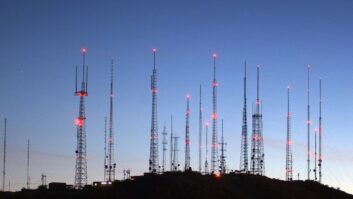
he existence of a negative tower in an array is one condition that seems to strike fear into the hearts of many station engineers.
So maligned are negative towers that they have become known as the bane of all things AM. They either are blamed for anything that goes wrong with an array, or are spoken of the way disagreeable neighbors are discussed. Admit it: You have made similar comments.
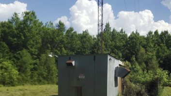
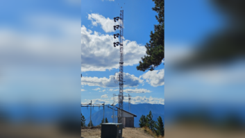
Fine weather and plenty of daylight make a great opportunity for the inspection of tower bases and ATUs.

The reality is that a negative tower can sometimes be a problem, but is not always so.
This phenomenon arises in a directional antenna system when the array is active. Each element, or tower, in the array has a self-impedance. This is the impedance of the tower by itself when the other towers are appropriately detuned from the array. When the array is active, however, the self-impedance of the towers changes as a result of the interaction between the array elements. Some configurations result in a situation where the resistance component of the impedance is less than zero. The result is this particular element delivers power back into the phasor, instead of the phasor delivering power to it.
A negative tower can be problematic when the value of the drive point resistance is close to zero ohms. In reality, towers with a near zero positive impedance are also problematic, as environmental or other factors can cause wandering of this value back and forth about zero. Such swings result in array instability, which manifests itself with parameters, including monitor points, frequently being found to be out of tolerance.
Many of the negative tower problems in old arrays have been reworked over the years. Their original existence, in some cases, is owed to lack of computing power, while in others, negative towers are a consequence of certain array geometries, and are not so easily eliminated.
Even in the simplest of array geometries, the in-line design, negative towers pop up frequently when the nulls are set forward of 90 degrees off of the tower line. To put it another way, consider a directional antenna comprised of three 90 degree towers with 90 degree array spacing oriented along an azimuth of zero degrees. If the array is designed such that the major lobe is at zero degrees, and the nulls are north of due east and west, then frequently, one of the towers in the array will be negative.
Over time, many arrays with these problems, and others, have been redesigned or reconfigured to reduce these, and other issues such as bandwidth. Old arrays with such problems may pose a special challenge, especially at night when the newer stations are accepting interference. The proposed changes in the AM protection rules may allow for the possibility of reconfiguring problematic arrays, especially for daytime operation.
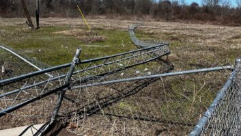
Tower bases should always be surrounded by well-maintained fences, and completely free of weeds, even with a skirted array.VERIFICATION OF EFFICIENCY

We are all familiar with checking monitor points to examine the condition of an array. Monitor points, though, are not really there for the benefit of the station licensee. Rather, they exist for the other guys on the frequency.
One of the stations owned by a group I represent has a monitor point on the tip of their major lobe during nighttime operation. This is a somewhat unusual situation, as monitor points are typically found either in, or very close to, a null. Because of their usual locations in a low signal region, it is usually assumed all is good with the pattern if the monitor points are well below their limits. That is not always the case, except for the other guy, because lower monitor point values imply a decrease in received interference.
Other than cases like the station belonging to my client, monitor point values generally do not tell you what is happening in the major lobe, which directly affects your coverage. I have generally agreed with the streamlining of the requirements for a partial proof of performance.
Indeed, the current AM revitalization order proposes further reductions in the requirements. The current rules require measurements on the monitor point radials. If the pattern has fewer than four monitored radials, then adjacent radials are to be considered. Under the current proposal, the adjacent radials would be eliminated, and only the monitored radials considered.
The problem with the current and proposed rules regarding partial proofs is they are geared towards the other guy once again.
By looking only at the monitor point radials, which are generally in the nulls, the radiation in the tips of the lobes may tend to be ignored. A significant reduction in the field strength in the lobe locations as compared to the previous full proof may be indicative of an efficiency problem with the array, which could significantly affect coverage. Unfortunately, by not requiring measurement of the main lobe radials, such a problem may lie unseen for a long time, which we will consider shortly.
To verify efficiency issues, several measurements should be performed in both the directional and non-directional modes. Half-a-dozen points are usually more than adequate to establish a trend. These measurements should be performed at known locations from the last proof, and the ratio between the DA and ND values computed. If the ratios are similar to those in the last full proof, then the observed problem of low field strength may be a conductivity change. An oscillation in the ratios is a good indication of re-radiation, which may also be seen by field strength peaks off bearing. Finally, if the DA to ND ratios are similar, but higher than at the last full proof, the radial looks to be hot, and the pattern is probably out of adjustment. If the converse is noted, then an efficiency issue should be considered.
Sometimes a change in the efficiency can be identified by a change in the base current values. The base current ratios, which are determined by dividing the base current at each tower by the base current of the highest current tower, will generally remain close to the licensed value if the pattern is correctly adjusted. A swing in the actual base current values, while maintaining the ratio, may be an indication of an issue with the antenna ground. A change in the currents is indicative of a change in the drive point impedance, which is impacted by not only the coupling between towers, but also the impedance of the tower by itself. Variations in the latter tend to arise from changes to the ground system.
Although less common today, an impedance shift in a particular tower could also be the result of the joints between the sections. All AM radiators should have the flanges between tower sections welded on at least two legs to ensure a solid connection. Sometimes this requirement was ignored, with the problems not developing until many years later after corrosion had started to set in on the connection hardware. A sudden shift in impedance on a tower that is known to have welded sections may indicate a crack in welds, which could be as simple as a defective weld, or more sinisterly a structural integrity problem.
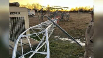
As ATUs get older, components age and become corroded; connections can loosen from daily heating/cooling cycles. Keep connections tight, and dirt out, to the extent possible.COMPONENT FAILURES

Several months back when we discussed capacitors, the recommendation was made to check capacitors at the very minimum with an LCR meter, and more preferably through an RF bridge. Interestingly enough, this very issue recently reared its head in a DA-2 array. One pattern was found to present a very high reflected power to the transmitter. Upon a visual inspection, a failed mica capacitor was found, and replaced. This returned the pattern to operational parameters close to the licensed values. The problem was that the high reflected power condition remained.
Based on these symptoms it would be expected that a component failure occurred in the common point trim circuit, or a sufficient number of components failed together to bring the phase monitor parameters to the licensed values, yet throw off the input impedance. Obviously, the former situation is the more plausible, and indeed that is exactly what happened. The mica capacitor in the shunt leg of the input network failed, however, to a simple capacitor checker, it presented the proper capacitance. When measured using both an RF bridge and a specialized AM network analyzer, the impedance of the capacitor was found to have a resistance component in excess of 60 ohms. Clearly, that is an undesirable condition for a part designed to provide an almost pure reactance.
One very basic method for checking the component integrity in an array is through heat. Components in an array may be warm to the touch, but any component that is hot to the touch is definitely suspect. It is understood that when testing via touching, the transmitter must be turned off and locked out. Only then should you carefully reach into a cabinet to check. Touching the components can be avoided if an infrared thermometer or thermal imager is available for use.
Finally, it is important to remember that while antenna systems do occasionally require a touch-up on the tuning, they tend follow a version of Newton�s First Law of Motion: Unless some force acts on the antenna system, it will remain in its current state. Reversing that force to bring it back to the desired state is the goal. Avoid applying other forces through blind adjustments, which will most certainly shove things into a different state.