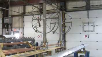
(click thumbnail)Fig. 1: Not only STL dishes but yagis can be used to couple across an AM base insulator.
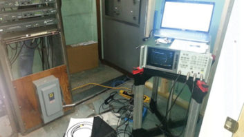
(click thumbnail)Fig. 2: DA common point measurements can be complex.
(click thumbnail)Fig. 3: Recent adjustments are handy thanks to shipping tags strung to the phasor cranks.
(click thumbnail)Fig. 4: Keep antenna feed-through insulators clean.The reliability of today’s broadcast equipment means many products are forgotten for many years – they just do their jobs over and over.
One of these is the Optelator from Stormin Protection Products. This protective device has been used in the AM/FM industry since 1998. The product uses a fiber-optic link to protect remote control modems from damaging surges. It’s a novel idea to separate the remote control/telco link with a fiber-optic link, and it works well.
However, like any product, it does need to be checked occasionally. For example, the batteries will wear out in approximately four years. Place a label to remind you when to install a fresh set.
If you operate a Sine Systems remote control, there is a modification that’s required if you use the Optelator II. Engineer Brian Hill from Back Yard Broadcasting in Williamsport, Pa., discovered a need to change the ring sensitivity of the Sine when using an Optilator. The reprogramming is straightforward.
On the RFC1B unit, access memory address 1014. Enter the value “10” and hit pound “#”. This changes the Factory Default of (0) = 1.79 volts sensitivity to a sensitivity of 4.66 volts.
After the reprogramming, the Sine connected on the first ring. There’s no worry that this change would permit transient surges higher than 1.79 to get through. Because of the fiber optic link, nothing above 4.66 volts will pass.
If you’re not familiar with this device or would like an online catalog, visit www.storminprotection.com
***
Jay Crawford saw our picture of two mini-flectors used to couple across the base insulator of an AM tower (Fig. 1). It reminded him of a similar project at WLW(AM). Back in the late 1980s and until the mid-1990s Jay worked for Jacor in Cincinnati, mainly as the chief engineer for WEBN, their local FM station.
He did some work on the WLW tower out in Mason, Ohio. The tower supported a shared Marti receive site, and as in Grady Moates’ STL application mentioned earlier, they also had to get the 7/8-inch line across the base insulator. The cable came down to a standard Marti 450 MHz yagi that was mounted to the tower. This antenna pointed to a second identical yagi mounted to the building, which housed the tuning unit.
That yagi was connected to the coax going into the transmitter building and the Marti receivers. This was a system worked up by Jay, WLW’s chief engineer at that time Paul Jellison, and Jacor Director of Engineering Al Kenyon. This site worked well and was fairly inexpensive to build. They realized the height advantage of the WLW tower as well as that of a site on the northern edge of Cincinnati area, which made a lot of remote broadcasts possible in the days before ready availability of POTS codecs and ISDN lines.
The “two-antenna” approach avoided the need for a high-power isocoupler or all the standoff/cable insulating that would have been required otherwise.
Jay now works for Cincinnati Public Radio.
***
I met Gary Keener back at the 1985 NAB convention. Though our career paths haven’t crossed since then, Gary reads Workbench regularly and runs Keener Technical Services in San Antonio. He adds a few thoughts on AM power determinations, a topic discussed in the Dec. 7, 2005 column.
First, the FCC requires you to tell them if you discover the AM tower resistance has changed. They require you to file Form 302-AM and tell them what the new resistance is and what the new current should therefore be. This action will cause them to issue you a new license reflecting the correct values.
When filing the form, include a short statement describing the test gear used and listing who the technician was. The station should be operated using the indirect method of power determination from the moment you discover the resistance has changed until a new license reflecting the change has been issued.
Once you’ve got their OK, you can “return to the direct method of measurement.” See §73.51(d-f) in the FCC rules for details. When filling out the form, there is still a place for the reactance, though this is no longer required. You can leave that measurement out if you want. The same is true for DA base currents.
As for DA common-points (CP), as seen in Fig. 2, the calculation is a little more involved. The correct common-point input power to a directional antenna system is the nominal power plus 8 percent for powers of exactly 5 kW or less. From 5.1 to 50 kW, it’s the nominal power plus 5.3 percent. And as we pointed out in our earlier discussion of tolerances, those percents are power percents, not current. So the correct maximum power input into a 5 kW DA would be the Pnom + 8% + 5%.
If you find that the CP resistance has changed significantly, obviously you need to go to the indirect method of power determination at that point; then find out exactly why. It’s likely to be a bigger problem than you think. Fig. 3 shows an inexpensive way of keeping track of previous and present phasor adjustments, contributed by Harry Bingaman of Sunbury Broadcasting in Sunbury, Pa.
Only when you’re sure the array is tuned up correctly and the CP is adjusted for the final R value should you file 302-AM. If the problem with the CP resistance was as big as the ones Gary’s firm finds, you might have to attach a partial proof of performance to the Form 302-AM. See §73.51(b).
Before you make DA adjustments, though, Gary recommends a thorough inspection of the RF components. Conducted when the transmitter is off – and bypassed so it can’t be accidentally turned on by an impatient jock – use a trouble lamp to visually inspect all components. While you’re at it, clean and tighten connections using fresh rags and isopropyl alcohol.
The parameter shift may be obvious: a burned coil clip, hung-up RF contactor or mouse or snake across a coil or capacitor. It may also be a loose connection that has heated; look for obvious discoloration. Remember that insulators can’t insulate when they are dirty, as seen in Fig. 4. Clean everything, plug holes in coupling networks and use a Sharpie or similar brand of marker on either side of a coil clip so if it falls off you know where it belongs.
Your AM station may measure power at the transmitter output terminals, and that’s fine, but only under certain circumstances. Naturally, the resistance measurement should be made at that point, unless you’re going to change the point of measurement. If you are, provide a schematic of the new measurement point. See §73.54(a).