Our picture of a “mystery” cable in the Aug. 17 column brought back a lot of memories. Many replies saw through my comment of using the adapter as a permanent fix for someone’s audio gear. The secret was the little tab on the “AC” plug.
Jerry McCarty at the University of Michigan says he actually never saw one of these, but he was familiar with remote mixers that used twist-lock connectors for the audio. This was before XLRs were standardized. Jerry also had seen adapter cables advertised for sale into the 1970s.
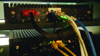
(click thumbnail)Fig. 1: It looks weird, but it was a lifesaver for surprises at remotes.
He did some searching but had just about given up when he came across an online copy of a 1969 instruction manual for a Shure M62V level controller on the electronics portion of the site www.freeinfosociety.com.
In the accessories section of the manual is a reference to an A68C adapter kit, which contained, among other things, a twist lock-to-XLR cable. So while the cable looks bizarre by today’s standards, Jerry writes that it was a lifesaver for surprises at a remote.
. . .
Dennis Gilliam, chief at FM stations KJZZ/KBAQ in Phoenix, writes from a different perspective.
He has the “other end,” a 1940 Western Electric 22B Portable Mixer. This equipment used the three-pin twist lock for mic inputs. So the answer was an “RCA-to-twist lock” as an input cable for a PA system or tuner.
. . .
(click thumbnail)Fig. 1A: Image from M62V manual, dated 1969.
George Waters, an engineer in Florida, had yet another take. He thinks he sees a ground pin on the “AC” end. If that’s the case, he postulates that the pin is connected to the sleeve of the RCA connector, and there is no connection to the center pin of the RCA, or to the AC itself.
The purpose would be to supply a ground to a piece of equipment that has no ground, such as the many pieces of consumer audio equipment that only use two-pin AC plugs. Interesting!
George writes that he’s reminded of an audio amplifier and accessory tuner that he owned in the 1950s. Each was built on an open metal chassis, with the tubes plugged in on the top surface. The tuner got its power from the amplifier via a plug-in connector.
For some reason, perhaps to save pins or avoid ground loops, the power connector carried DC power only. The ground return was the RCA audio connector, which carried the audio from the tuner to the amplifier.
George found out the hard way when he unplugged the audio cable to reroute it, then put his other hand on the chassis to steady it as he plugged the connector back in.
. . .
(click thumbnail)Fig. 2: Your points are never lost with the FIM-4100.
Fred Shetler from Port Royal, Pa., correctly identified the connector as a threeprong twist lock, adding that it could never fit in an normal AC outlet. He also saw the connector used as a mic connector many years ago.
When he was working for WDAD(AM), the Collins 12Z Remote Amp had the connectors modified to the twist-lock style. All the station mic cables had this style connector also.
Fred adds that he did the church remotes for years and used them every Sunday.
. . .
Gordon Carter, chief at Chicago’s WFMT(FM) and the WFMT Radio Network, urges readers to think older.
He remembers when the twist locks were used for mic connectors, too. He adds that the adapter cable could have been used to adapt a line-level source, like a consumer tape machine, into the mic input. Gordon writes that there might be a couple of resistors under the tape, making a simple “L” pad, to reduce the level!
. . .
And Ben Dawson, principal engineer at Hatfield and Dawson, weighed in, remembering at least two kinds of “twist-lock” connectors, one the type seen in Fig. 1, another that had a barrel/cavity with the connections on the sides. Both kinds, he said, were used as audio connectors.
(click thumbnail)Fig. 3: Front-panel display of the FIM-4100
Ben was the first to identify the connector properly as a three-terminal “Hubbell twist lock.” He writes that not only were they occasionally encountered as microphone connectors in old studio and semipermanent remote installations, they were used along with Cannon “P” connectors and even three-terminal Jones plugs. He thinks the cable may be a relic from a poor soul in the 1950s or ’60s who was trying to get some awful Webcor or Tandberg radio to put out audio in his antique production room.
Ben adds that getting to or from a 50-ohm low-level input/output to Hi-Z RCA pin plug is a little odd but not unreasonable. Remember that Motorola – and Moseley, when it remarketed chassis it bought from Motorola – used RCA pin plugs for 950 MHz RF connectors!
The RCA pin plug is one of the finest examples of cost-effective design Ben’s ever seen, and he still hates them.
. . .
The last quarter will be here before you know it. Now is the time to start your wish list for capital improvements.
If you handle AM stations, particularly directionals, here’s a product you must consider. It’s a new AM Field Strength Meter, Model PI-4100, manufactured by Potomac Instruments; it earned a Radio World “Cool Stuff” Award this spring.
Potomac has ended the problem of finding monitor points. It combined GPS, compass, self-calibration, digital tuning, and data acquisition and storage capability. This last feature anticipates the future acceptance of e-filing of data by federal regulatory agencies.
An expanded view of the screen is shown. You can get a PDF of the data sheet by heading to www.pi-usa.com.
. . .
A reminder: Don’t forget about entering our do-it-yourself circuits contest. We’ve got engineering-themed T-shirts to be awarded to the three best “home brew” circuit projects, courtesy of the NAB Store.
Your submission can be an equipment modification that improves performance or a bread-boarded circuit that solved a problem at your stations. E-mail or fax your entry using the information below. Be sure to include a clear drawing of the schematic, a high-resolution digital picture of the device, a parts list and a description of what the circuit does.
It’s an opportunity to put a few bucks in your pocket, a shirt on your back and credit toward SBE recertification on the books.
Faxed submissions can be sent to (603) 472-4944. Submissions for this column are encouraged, and qualify for SBE recertification credit.