Fred Baumgartner writes from Colorado to tell us that Charlie Sears, the transmitter engineer for WTTV(TV) in Indianapolis at the turn of the current century, built and used DIY surge protectors on all phone lines coming into his transmitter facilities.
Fred has done the same ever since, using them on any twisted pair — audio, data, etc. — exposed to lightning-induced pulses. Many transmitter sites still retain POTS lines for emergencies, and some have twisted pairs (not Ethernet) between buildings.
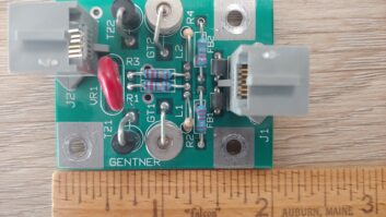
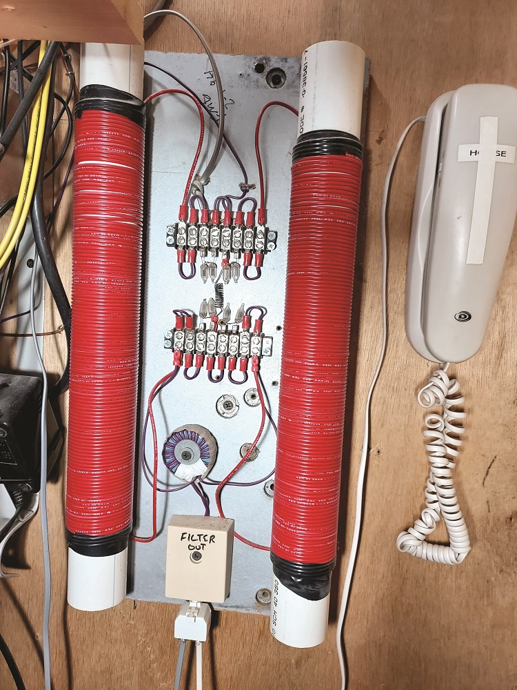
The protector in the photo is 30 years old; Fred uses it at home to separate his house and Vonage IP/telephone box from the more exposed lines to the outside ranch buildings.
Without protection, Fred says, his telephone-connected gear routinely was destroyed by lightning. Since he began installing these decades ago, he has not suffered equipment damage.
Construction is as simple as it looks. There are no magic component values. The more turns on the chokes the better:
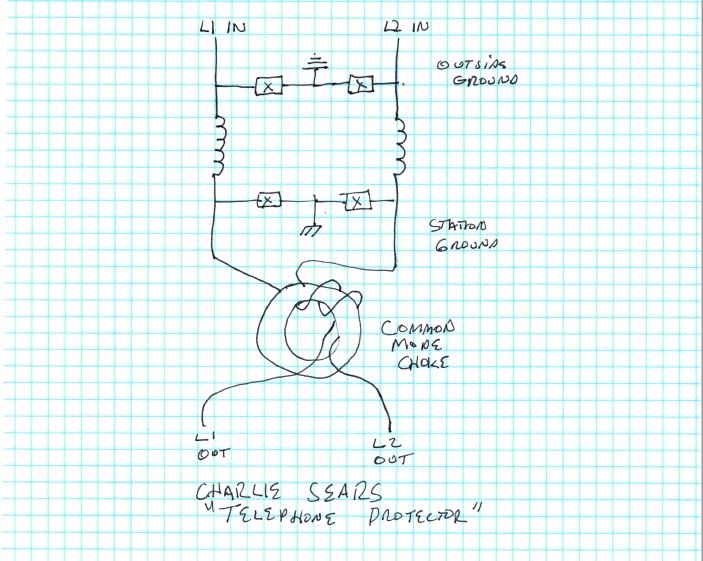
Charlie used two 2-inch PVC pipes for the inductors. Wire was whatever was on the bench. The common mode choke (toroid) is on a “mystery” core from a hamfest. The four “X” surge suppressors are most often two NE-2 neon bulbs in series (they will light up when the line rings, and if they do not, you can go to parallel NE-2s).
Other lower-voltage surge suppressors typically use varistors, MOVs or gas discharge tubes, when the lines are low-voltage control or inter-building audio.
Referring to the schematic, the output side ground is the building common ground, while the input side ground is typically the phone company’s shield (which is found on direct burial multi-pair phone wire).
Fred’s own occasional modification is to place 100 mA fuses at the inputs, but they are no longer readily available, and you would need to replace them with some regularity. Fred doubts the fuses ever really helped.
Goo, gone for good!
Reader Mark Peterson sent in a note that if you are trying to remove adhesive residue, like the globs of tape scum from the sides of that Western Electric 111C, head to Walmart or similar retailer and buy a bottle of GooGone goo and adhesive remover. This compound costs less than $5 a bottle. It’s also useful for removing the sticky residue from cables secured to the floor by duct tape.
Crown amplifier guide
From Florida, Wayne Eckert sends a link to a useful guide from the Crown Amplifier division of Harman.
While the intended readership is sound support and PA system technicians, the information it contains, especially the connector wiring guides, will be useful to broadcast engineers. The 35-page guide is thorough when it comes to amplifiers, a great tutorial or refresher. Just a sample is shown here.
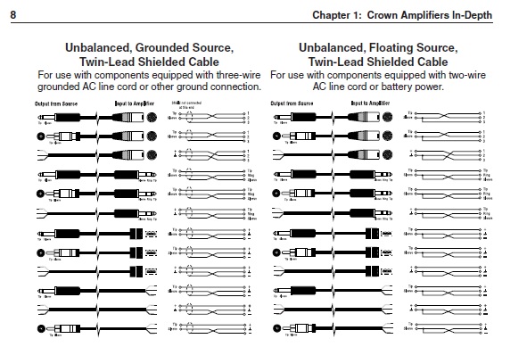
One section that caught Wayne’s eye was a warning about wiring up speakers and amplifiers using connectors that could be plugged into AC power sockets! Accidental AC input will be an electrifying experience for your equipment. (But, Wayne adds, you will find out real quick if your speakers are any good at 60 Hz!)
Download your copy at https://help.harmanpro.com.
Speaking of audio
Paul Sagi in Malaysia writes that he was fortunate to have an oscilloscope with a Z-axis input on hand while working in an audio repair shop years ago. Check your ’scope for a Z-axis or X-Y mode. If present, use a signal or function generator to set up a Lissajous pattern display on the scope screen.
The Z-axis or X-Y mode permits display of the Lissajous pattern in three dimensions. The glowing green rotating pattern looks striking — to those unacquainted with Lissajous figures, it seems totally surreal.
Having this “screen saver” caught the attention of many customers, mesmerizing them. It can do the same for your air staff and management! Google “How to Make Lissajous Patterns” on YouTube for a more detailed setup and demonstration.
Blowin’ in the wind? Oui oui!
A reader who shall remain anonymous says he enjoyed reading about the Cumulus site in Washington where engineers signed the floor each time a new transmitter was installed. He shared this story:
On top of the IDS Center — the tallest building in downtown Minneapolis and home to multiple FM signals — there apparently is or was a list of names, written on a ledge in front of a microwave dish. It is a list of engineers who have relieved themselves off the top of the 57-story building at the conclusion of a project. (And, according to further legend, the first name was female.)
Our reader adds that after hearing this story, every time he walked the sidewalks of downtown Minneapolis he wondered about any drop of moisture he imagined he felt!