 The author is owner of Rural Florida Communications Cooperative. He is a retired AT&T employee who has a great deal of experience protecting communications facilities from lightning and surges. He saw Mark Persons’ recent account in Radio World of a lightning strike to the pole supporting the KRJM STL antenna and was inspired, first, to provide some tips for John Bisset’s Workbench column in the Dec. 9 issue, then offer the following in-depth article for readers of RW Engineering Extra. We in turn are inspired to share it with you.
A wise man who invented the air terminal, Benjamin Franklin, once stated, “An ounce of prevention is worth a pound of cure,” and the lightning damage at KRJM bears witness to that.
Now, let me start with dispelling an old myth. I have heard from a number of engineers that “If you take a direct hit, it’s all over; there is nothing you can do to prevent that.”
Such a statement is patently false. The Tier 1 Carrier I retired from has tens of thousands of cell sites and switching offices all over the U.S., and they take thousands of direct hits annually without sustaining any damage at all.
Why? Because we engineer layered lightning protection into each site. Be it standalone, collocated on a broadcast tower or on a rooftop, proper protection equals greatly lowered losses and greatly increased uptime.
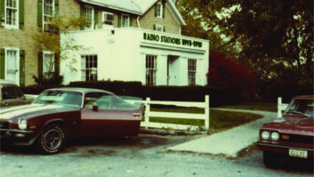
So how is this done? Well, let’s use the example of KRJM(FM), which Mark Persons wrote about in “What Happens When Lightning Hits? A Case Study,” which appeared in Radio World in October, and which you can find at radioworld.com by searching for keyword KRJM.
Beginning with the improperly protected and grounded pole and ending at the last burned-out device, this is a perfect example of where an ounce of prevention could have prevented a lot of heartburn.
Let’s start with the pole. When I see a pole shelled out from lightning, the first thing I look for is a down conductor. I could be incorrect, but I don’t see one on that pole.
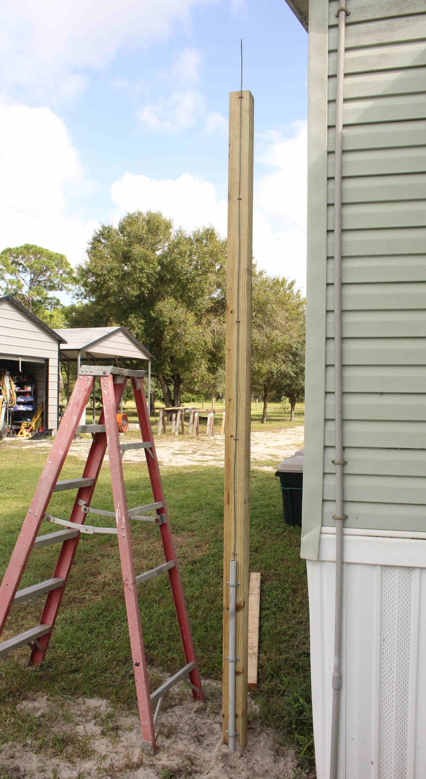
A down conductor is a simple lightning protection device. Before the pole is placed, an AWG #6 hard-drawn copper conductor is placed on it using fencing staples, attaching it from the top of the pole to the butt. The installer leaves six or so inches of the conductor standing above the top of the pole and coils up a few feet of it on the butt, starting in the center, and where the conductor crosses over itself, places a staple diagonally to connect the two conductors to each other.
The goal is to produce a low-resistance, low-impedance grounding electrode on the butt of the pole. When the pole is placed in the mounting hole, it will make good contact with the earth, producing a good solid grounding electrode.
The down conductor provides a bypass for the lightning energy to earth, sparing the pole and any attachments from damage. See Fig. 1.
If the pole is already placed, a down conductor can be added by placing a ground rod with a minimum length of eight feet into the earth.
One important note: Always call for a utility locate before driving a ground rod or doing any digging. In most states, the number is 811. Failure to do so can get you killed, or if you survive hitting a buried utility line, the least you’ll get is a substantial bill from the utility for the underground damage you caused.
The installer then installs the down conductor in the same manner as a new pole, minus the below-grade work, connecting the down conductor to the grounding electrode.
All that protects the pole, but what about attachments?
The first step is to bond all attachments to the down ground lead with an AWG #6 copper conductor. That’s your first layer of protection.
The next step is surge protection, commonly referred to as Transient Voltage Surge Suppression.
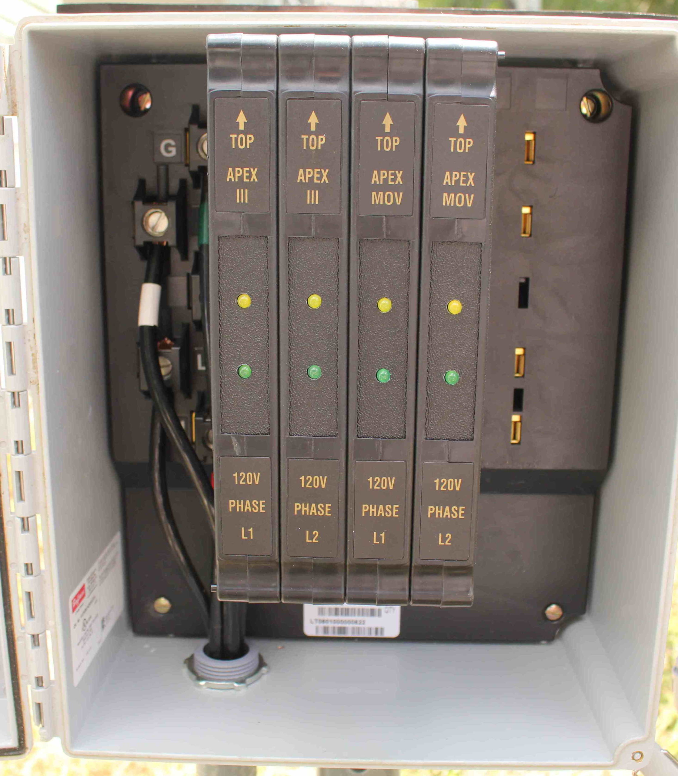
A TVSS can be installed in one of two locations. The best location is where the cables coming off the tower or pole enter the building. However, if the building is metal, it is better to deploy a primary TVSS near the base of the pole or tower.
If the TVSS is rated for outdoor installation, a cabinet is not required. However, most of the time you will want to keep the TVSS in a dry location and out of sight.
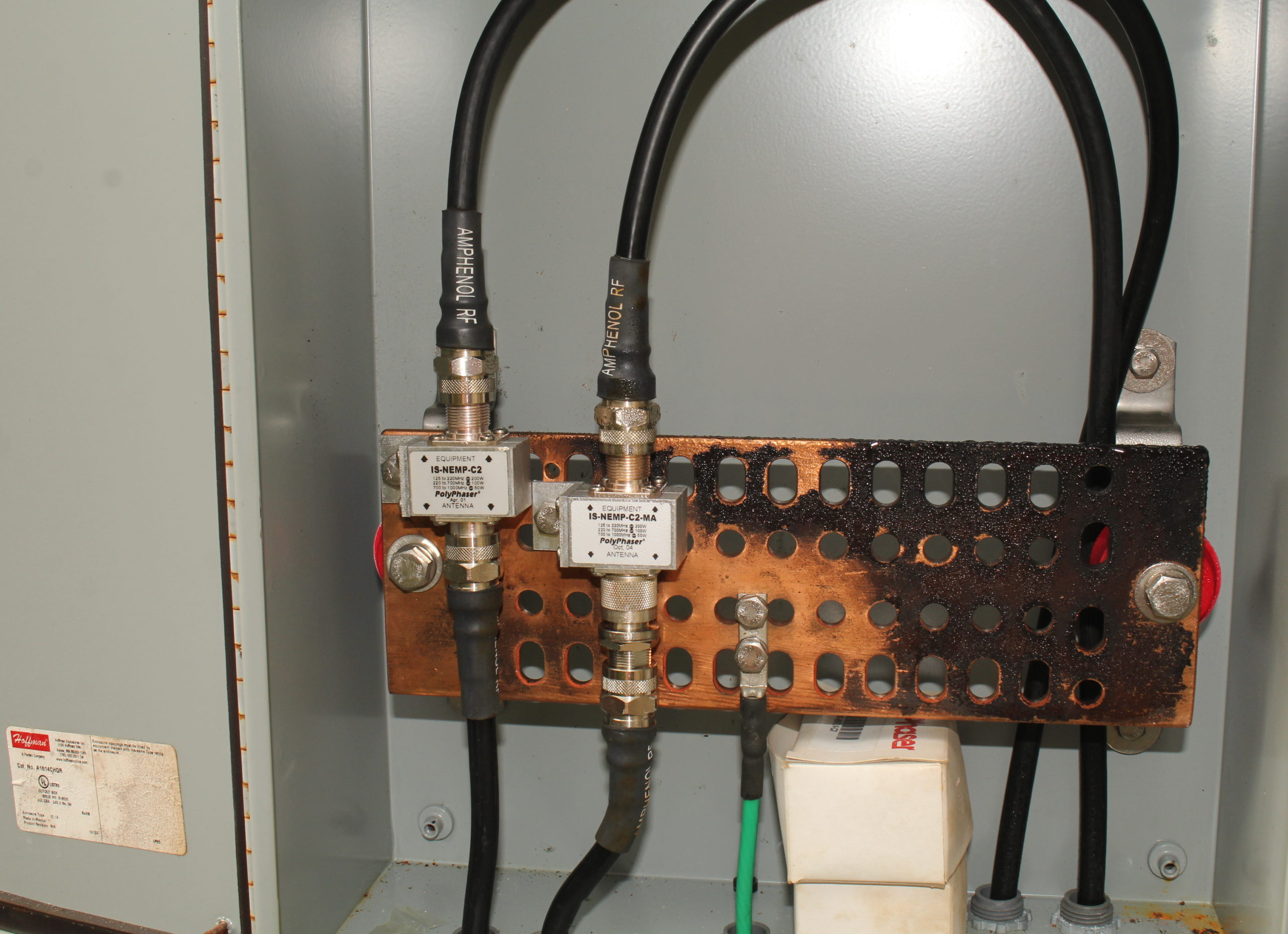
Either way, the TVSS should be installed on a common insulated buss bar. This bar should be bonded to the pole or tower ground and grounded to the main grounding bar (MGB) in the building. The minimum recommended grounding conductor is AWG #4 copper, unless the distance between the pole ground bar and the MGB exceeds eight feet. Then it should be stepped up to an AWG #2 copper conductor. See Fig. 2.
Bringing It Inside
The common method when bringing cables into a studio or transmitter building is to use a bulkhead. This can be as simple as a sheet of nonflammable water-resistant material such as Hardie Panel sheeting or acrylic plastic.
In a metal building, this is mandatory. You do not want to penetrate a metal building where a cable can be in direct contact with the metal wall. That is begging for arc-over problems.
[Subscribe to Radio World Engineering Extra.]
The point where the cables enter the building is where you will place your primary or secondary TVSSes. The MGB should be placed as close as practical to this penetration, but no more than a couple of feet away.
Each TVSS should be connected to the MGB with its own grounding conductor. Never double up grounding conductors. The grounding conductors should be placed either right or left of the center of the MGB. The conductors should be swept in from above and not reversed below and upward where they connect to the MGB. The primary grounding conductor for the MGB should be connected at the center of the MGB.
The reason for connecting the main grounding conductor to the center of the MGB is to isolate incoming conductors that introduce surges on a regular basis (dirty) from the sensitive equipment (clean), which must also be connected to the MGB to be protected.
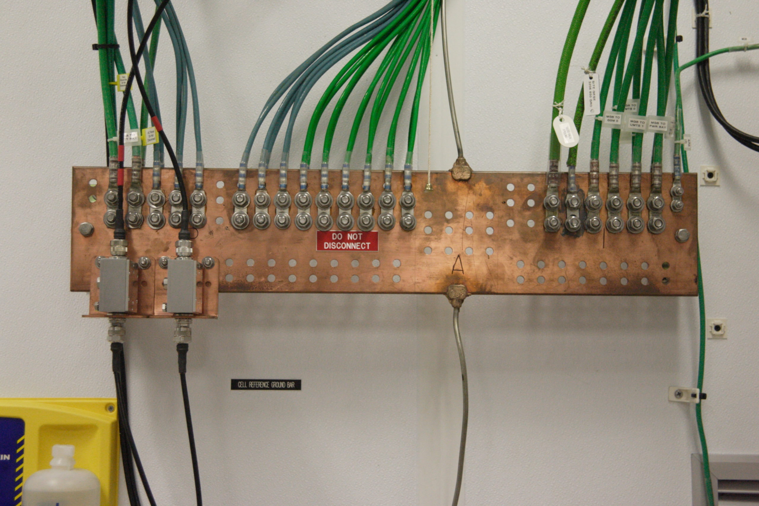
The center MGB ground serves to provide this grounding isolation or PANI, an acronym describing a way of bonding conductors to the MGB in a specific order, depending on their origin: surge energy Producers, Absorbers, Non-isolated equipment and Isolated equipment (Fig. 3).
Power and Utilities
More commonly than not, the power, telco and CATV are not going to enter the building at the same location as the cabling off of the tower or pole, but they must also be protected, so let’s start with power.
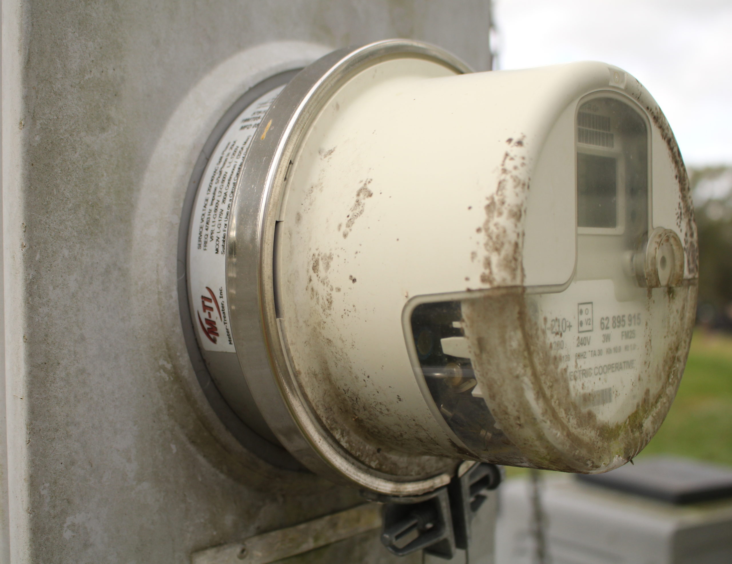
Your building will have a watt-hour meter, and it’s usually installed outside (Fig. 4). Even if it is a “smart meter,” it’s a simple device that allows your electric utility to vacuum funds out of your bank account and transfer them into the utilities bank account. However, that watt-hour meter can be used to your advantage.
There are devices known as meter-based TVSSes, which are sleeves that are installed by either a licensed electrician or the utility between the meter base and the meter. Some utilities will allow your electrician to do the work; others insist that you rent the TVSS from them for a small monthly fee. Either way, they are good protection for the cost. They are crude first-line devices that can take the brunt of a hit.
But don’t stop there. Always have a hard-wired TVSS installed as close as possible to the service entrance. Some will require a circuit breaker to be installed ahead of the TVSS to prevent a catastrophic burn-down of the TVSS should it go into a total failure after doing its job.
That breaker should be installed as close as possible to the main breaker in the service panel. If that requires moving breakers around to clear a double space, so be it. If the service panel is choked up with no spare spaces, drop in a sub-panel and unload other circuits to the sub-panel to make space for the TVSS breaker.
Do yourself a favor and don’t go cheap. Real TVSSes for power run anywhere from $400 to $2,500+, depending on the rating of your service entrance and if it is single phase or multiphase power (Fig. 5).
On the Inside
If you have a load center within your building, this is a great place to add a secondary panel buss TVSS. While not breaking the bank, most manufacturers of load centers offer TVSSes that simply slot in like a multipole breaker. Like a primary TVSS, they should be installed next to the feed to the panel. If needed, have your electrician relocate one or two breakers to clear up slots and you are good to go. See Fig. 6.
Moving down in voltage, we have telco, cable and CATV. These incoming services need to be protected as well.

Normally your telco provider will provide a network interface device (NID). Within it will be protectors, commonly gas-based protectors with a 400 VDC breakdown. As long as the NID is properly grounded and bonded to the building’s ground system, that provides good primary protection. Internally, you want to back that up with TVSSes rated for no more than 200 VDC for POTS phone lines. Special circuits, however, are a horse of a different color. Digital or audio circuits behind the telco’s mounting need to be protected by very low-voltage TVSSes, 50 VDC or less.
Commonly, cable and CATV will utilize a spark-gap protector, and like telco, it must be grounded and bonded to the building’s grounding system. However, a spark-gap protector is unsuitable in this application. Back it up with a reputable coaxial TVSS mounted to the dirty side of the MGB ahead of the distribution of the cable or CATV signal within the building.
Grounding and Bonding
Now, for a somewhat more complicated subject, grounding and bonding. It is extremely important that all connections to earth be bonded to each other. Lacking that bonding, surges entering your facility over various services connected to disparate earth connections will wreak havoc within your facility.
|
An example would be if your facility was not built from the ground up as a broadcast facility. While the structure is wired to code, you later add something simple such as a DTV or other satellite dish.
That dish must have a clear view of the southern sky, but your electrical service and other utilities may enter a different side of the building, say the north side. Not a problem.
The contractor for the DTV provider or the dish installer installs the dish on the south side of the building’s roof, then runs the coax from the dish down and through a spark-gap protector, which is earthed to a ground rod he placed. That ground rod, however, is commonly not bonded to the building’s grounding system by the contractor.
Later, during a storm, lightning tickles that dish. The resulting energy saturates the unbonded ground rod and the remaining energy seeks out all other forms of an earth ground it can find. In the process, it passes through the connected receiver and then enters the building’s electrical system. From there it passes through and into any source of a ground to earth. This would include neutral, any electronic device with a three-wire cord, or grounded rack-mounted equipment. Sometimes lightning energy will find a ground just by arcing within the building’s wiring system and devices, destroying them in the process.
The solution to preventing such damage is to bond all connections to earth to each other with a minimum of an AWG #4 direct-buried copper conductor. This provides a low-resistance path from all grounding connections to earth, eliminating any differences in voltage potential between those connections.
Yes, all those connections may become saturated for a moment, and yes, there may be substantial rise in potential on all of them, but the bonds prevent any flow of energy through the protected equipment within the structure.
Comment on this or any article, email [email protected].