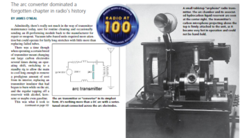
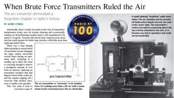
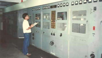
![]() Admittedly, there’s really not much in the way of transmitter maintenance today, save for routine cleaning and occasionally sending an ill-performing module back to the manufacturer for repair or swapout. Vacuum tube-based units required more attention but could operate for fairly long stretches with little more than replacing failed tubes.
Admittedly, there’s really not much in the way of transmitter maintenance today, save for routine cleaning and occasionally sending an ill-performing module back to the manufacturer for repair or swapout. Vacuum tube-based units required more attention but could operate for fairly long stretches with little more than replacing failed tubes.
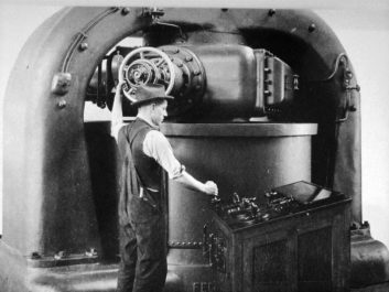
There was a time though when operating a certain breed of transmitter meant changing out large carbon electrodes several times during an operating shift, switching to a standby rig to allow the main to cool long enough to remove a prodigious amount of soot from its interior, replacing an transmitter insulator that had begun to burn while on the air, and the regular topping off a reservoir with alcohol, kerosene or maybe even gasoline.
This was what it took to keep the kilowatts on the air some 100 years ago. I’m referring to the Poulsen arc converter technology for generating a continuous carrier wave.
PUTTING A NUISANCE TO WORK
Most readers will have witnessed what happens when a path is abruptly broken in an energized circuit (anything from opening a knife switch to using a screwdriver to discharge a large capacitor). There is a bright flash of light and (depending) on the amount of voltage and current involved, a sound anywhere from a small “smack” to that of a lesser thunderbolt. The phenomena involved is an electrical arc — a flow of relatively low-voltage, high-current across an open space.
It was at one time (in pre-incandescent lamp days) used for artificial lighting, and even after the advent of the Edison lamp, served for several decades as a high-intensity light source in motion picture projection and some large spotlights.
Today, the electrical arc comes in handy for welding, “electro-erosive” fabrication of metal parts, and melting metals in high-temperature furnaces. Otherwise it’s a sometimes dangerous and expensive nuisance that occurs when relay contacts open or screws aren’t snugged down tight in power panels.
Early in radio’s history, however, the electrical arc was at the core of some of the most powerful transmitters ever put on the air.
NOT TO BE CONFUSED WITH “SPARK”!
Now, I’m not referring to the big “rock crusher” spark transmitters championed by Marconi and others in radio’s caveman days. Those were rather diametrically opposed to arc technology, as their operation involved relatively low currents and very high voltages (tens of thousands), and generated a “damped” wave oscillation that produced a very wideband (spread spectrum) type of signal.
Arc transmitters, or “converters” as they were known (they converted DC into radio-frequency AC), with the exception of the very large devices, typically operated with potentials of a few hundred volts and currents usually measured in the hundreds of amps.
The Marconi “rock crushers” were fine for communication via telegraphic code (well, not really, but they got the radio industry started). However, for Reginald Fessenden and other visionaries who desired to transmit speech and perhaps music, they were useless as the damped oscillation (think ringing a bell) produced was not suited as a carrier wave that could be modulated with an audio component.
Fessenden solved the problem of generating a continuous wave by pressuring the General Electric folks to produce an alternator that spun fast enough and had enough poles to generate an output in the LF portion of the radio spectrum. That took time, and it was not cheap either.
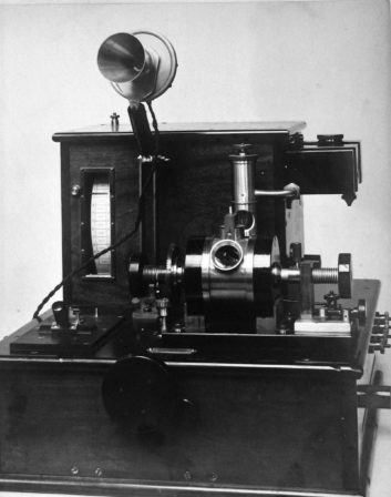
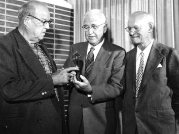
Courtesy of History San José
Elsewhere, others explored the production of continuous radio waves — or, as they were called back then, “undampt” waves — and found that a certain property of the electrical arc made it a good candidate.
Arc transmitter technology stemmed from the discovery by English physicist William Duddell in the 1890s that if a series-resonant circuit was connected across an arc, an oscillation developed, with its frequency determined by the external inductance and capacitance. Following in Duddell’s footsteps, Danish inventor Valdemar Poulsen (also the inventor of magnetic recording) made improvements on Duddell’s “singing arc.” He secured a patent for his work in 1903 and began marketing the first arc transmitters.
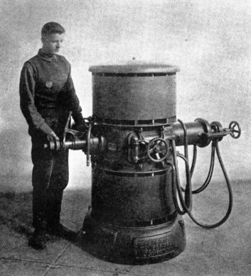
Courtesy of History San José
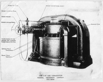
The technology formally arrived in the United States in 1909, when Cyril Elwell, a recent Stanford University engineering graduate who had done work in the field of electrical arc furnaces, became interested in Poulsen’s technology and secured patent rights to manufacture the transmitter. This Palo Alto, Calif., venture was originally known as the Poulsen Wireless Telephone and Telegraph Co., but later changed its name to the Federal Telegraph Co., and manufactured arc converters in varying sizes until the arrival of the high-power vacuum tube transmitter in the early 1920s.
HOW DOES IT WORK?
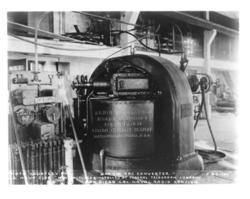
Courtesy of History San José
It’s useful to consider the physics of the arc converter (transmitter). While striking a DC arc is a simple and basic exercise — momentarily pushing energized electrodes together and then separating them to create the arc — putting it to use in making radio waves involves an understanding of the physical phenomena surrounding such an electrical discharge.
The most intriguing (and valuable) aspect of the arc is that it belongs in the category of devices possessing “negative resistance” characteristics. These include tunnel and Gunn diodes, vacuum tubes when operated under certain conditions (the dynatron oscillator), neon-filled tubes and lamps, and even ordinary fluorescent lamps.
True to Ohm’s law, when the voltage across an ordinary resistor increases, the current flowing through it increases proportionally (I=E/R). The opposite occurs in negative resistance devices; an increasing voltage results in lowered current flow through the circuit.
Courtesy of History San José
And while this sounds like a violation of physics, a negative resistance, in a way, produces power, rather than consuming it, as would a carbon resistor. Without getting too technical, in an arc converter, the negative resistance characteristic of the arc counteracts the positive resistance associated with the series-resonant circuit connected across it, thus maintaining its oscillations, which would otherwise die out in short order. (The same principle as in conventional radio transmitters in which an amplifying device [tube or transistor] supplies energy to sustain tank circuit oscillations.) While not a perfect sine wave, the arc converter’s oscillations are pretty close, and can serve as a carrier wave.
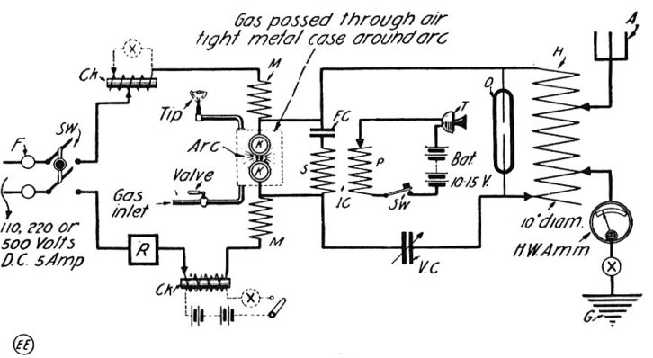
Actually, it’s not quite that simple, as more enhancements (add-ons) are necessary to make a truly practical and workable arc-based transmitter. A powerful magnetic field and a continuous source of hydrogen are also necessary. The magnetic field is needed to “blow out” the arc during an RF cycle and the hydrogen is used to help residual ions from around the arc electrodes during this once-per-cycle downtown.
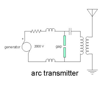
As seen in the above diagram, the electrodes are connected in series with the windings of the electromagnet so that when the arc is struck, the magnet is energized and blows out the arc, which in turn extinguishes the discharge. Heat and a few residual ions ensure that the arc is immediately re-struck as soon as the magnetic field is dumped. Of course, all of this is happening at an RF rate, so the arc would appear to be continuous to an observer. (Refer to the “Physics” sidebar for additional details.)
Note that even though the arc is being extinguished and re-lit during an RF cycle, the converter could not be “keyed” for radiotelegraphy in the same manner as other sources of radio-frequency energy, as the time interval between the “dits” and “dahs” would be far too great and the arc would have to be manually reignited.
This was solved, in what today would be a rather inelegant way, by connecting the telegraph key across a portion of the RF inductor used to set the transmitter’s frequency. During “key down,” turns would be shorted out, shifting the frequency higher. (With the really big converters and their accompanying very large RF currents, a relay with correspondingly heavy contacts was used. This is shown at the bottom right in the above diagram of a large U.S. Navy converter.
Of course, this frequency-shift keying used twice the amount of spectrum, but in the 1910s and 1920s, who cared?
(My own early mentor, who was born in 1904 and developed an interest in radio during the period when arc converters ruled the airwaves, recalled that the really good radiotelegraphy operators could copy this “back” or “compensating” wave as it was called, with equal dexterity, listening for the “holes,” rather than the carrier.)
A “workaround” of sorts was eventually devised to conserve spectrum, but it was somewhat cumbersome and not employed everywhere. This involved dumping the converter’s RF into a dummy “antenna” (load) during “key up” conditions so that only the transmitting frequency reached the antenna.
TRANSMITTING SPEECH AND MUSIC
Early on, experimenters found that the continuous wave output of the converters could be modulated with speech. Elwell used this feature to advantage, establishing a two-way radiotelephone service between Sacramento and Stockton, Calif., in competition with Ma Bell. It was claimed that the wireless audio quality was better than that of the wired service.
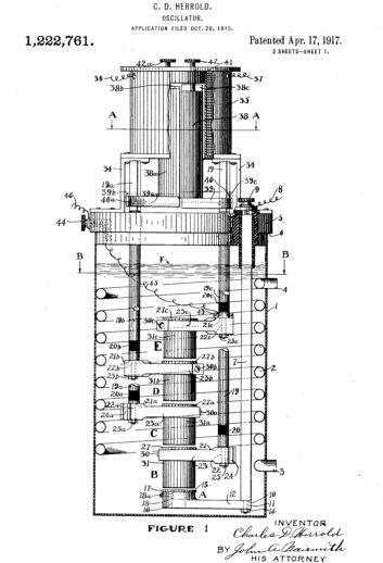
Others, most notably Lee De Forest and Charles “Doc” Herrold, began broadcasting speech and music via arc or “arcphone” transmitters. However, as pointed out, the machine’s output, if close to a sine wave, was not exactly; and the center frequency, if close, did vary a little. Early adopters referred to this as “fuzz” or “hair” on the signal. Today, we would likely refer to it as phase noise.
Courtesy of History San José
(Although not stated in his patent claims, Herrold may have burned his arc under water in an attempt to filter out some of the fuzz and possibly to supply the needed hydrogen through electrolysis.)
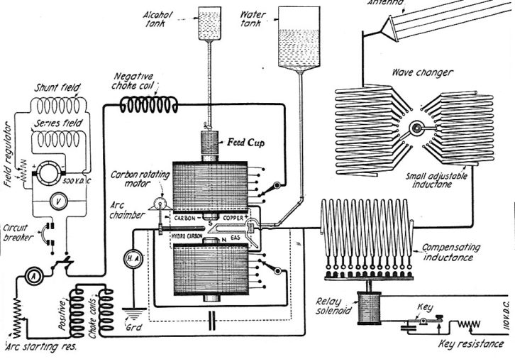
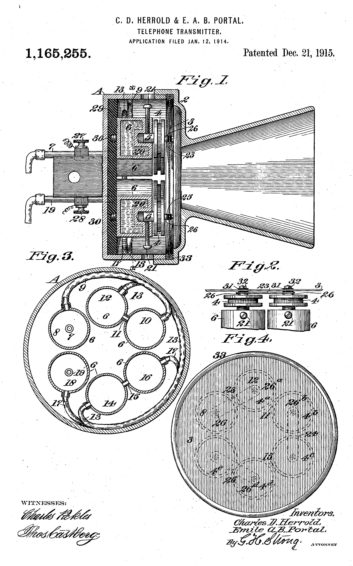
Audio modulation was achieved by simply connecting a carbon microphone (telephone “transmitter”) in the antenna or ground leg of the transmitter output. (Fessenden modulated his high-frequency alternator in the same fashion.) The varying resistance of the microphone element with sound produces a corresponding change in antenna current. Of course, with higher power converters, some means for dissipating the I-squared-R losses in the carbon element had to be provided, with solutions ranging from a water-cooled mic, the use of multiple microphones connected together, and even a “lazy Susan” arrangement for rapidly switching a fresh mic into the circuit while the one previously in use cooled down.
GAS ON THE FIRE
Early on, the upper frequency of the arc transmitter’s oscillations was limited by the curve describing the negative resistance; however, it was discovered, likely by accident, that introduction of a hydrocarbon-containing vapor or substance (it was actually the hydrogen component) greatly enhanced the performance of the arc and could move its frequency upward.
As the arc transmitter technology progressed, a number of hydrogen-containing substances were tried, including alcohol, kerosene, methane, acetylene, hydrogen gas and even steam. Interestingly, the converter’s operating frequency range could be shifted by substitution of these liquids, gases or vapors. (Of course, the operation of an intense source of heat in close proximity to flammable compounds was not without risk, as will be pointed out later.)
Ethyl alcohol seemed to be the favored hydrocarbon, at least for the lower-powered arcs, and one can’t help but wonder if this might not have been an added incentive when looking for employees to pull an overnight shift at the transmitter site. The alcohol used was likely pure 200 proof ethanol, or close to it, as “denatured” alcohol didn’t come into widespread use until after the Volstead Act ushered in prohibition in 1920.
TRUTH IN ADVERTISING
It should be noted that while the arc converter was a simple way of transforming DC into radio waves, its operating efficiency was not that great, bordering at best around 50%, so with the larger units, a carefully engineered cooling system was essential.
Also, Federal, likely bolstered by their ad agency, seemed to overlook this efficiency factor in their product catalog. For instance, their “one megawatt” converter actually delivered only about 500,000 watts of RF. The rest of the DC power had to be dispersed as heat, and just as in “modern” vacuum tube transmitters, the water-cooling system had to be electrically isolated from the converter’s copper anode. In the very high-power installations, this required two cooling loops with a heat exchanger and an outdoor “spray pond” in the secondary loop.
OSHA, PLEASE LOOK THE OTHER WAY
Obviously, the high-voltage, high-current potentials (typically from 500 to 2,000 volts and upwards of 500 amps, depending on converter output power) employed in larger arc transmitters were dangerous to the point of lethality.
However, arc transmitters posed another very serious hazard to life and limb. This was their propensity to explode violently if operating instructions weren’t followed to the letter, due to the aforementioned requirement for the continuous introduction of hydrocarbon-containing compounds into the arc chamber.
Precautions against the electrocution threat included these words to the wise: “Great care must be taken by operators working about an arc in operation, and any part of the oscillatory circuit, starting from the copper, must be avoided. An operator at one high-power station on the Atlantic Coast once started to refill the alcohol feed cup from a large metal can while the arc was in operation — he never did it again.”
Equally lethal accidents, but not always causing immediate death, included opening the arc chamber while the converter was in operation, or even after it was shut down if a prescribed amount of “cooling down” time was not observed. Violation of this rule could result in the transmitter literally becoming a “flame thrower.”
“Another stunt to be avoided is the opening of the arc chamber door immediately after the arc has been extinguished, for the sudden contact of the internal heated hydrogen with the external atmosphere will cause an outburst of flame which may result in severe burns to anyone within range. With large arcs, a period of ten minutes should elapse before the door is opened.”
The “always read the instructions completely before plugging it in” type of disclaimer also included the following, hopefully circumventing a slightly different type of “flamethrower” event:
“At least one fatality and several serious injuries have come to the attention of the writer owing to the operator having ‘struck’ the arc when the carbon [electrode] had not been properly fastened in its receptacle. In these instances, [with] the hydrocarbon gas having reached a sufficiently great pressure, the loosened carbon was blown out of its holder followed by a stream of flame, proving disastrous to the operator, who invariably stands on that side of the arc when starting it.”
Courtesy of History San José
(Another precaution was offered for those working around the giant “converters” that would be of little worry in today’s world of quartz-movement clocks and watches. This was the avoidance of bringing one’s prized timepiece near an operating converter, as the intense magnetic field could permanently damage the steel mainspring-driven movement.)
There were a number of early arc converter martyrs, and doubtless the list would have kept growing if the technology had not been pushed out of the way by the perfection of the vacuum tube as an RF oscillator and power amplifier in the 1920s. Actually, as late as 1922 — at least according to a U.S. Bureau of Standards publication that year, the arc was still the “go-to” source for high-power long-distance communications, with an estimated “80 percent of all the energy actually radiated into space for radio purposes during a given time” emanating from arc transmitters. (This excluded amateur stations, which still largely utilized damped wave spark apparatus.)
LIFE AFTER OBSOLESCENCE
Once more modern and efficient ways of producing a continuous wave emerged, not all of the dangerous, and sometimes problematic, arc converters were reconciled to the metal recycler. At least one, and probably more, were tapped for nuclear research.
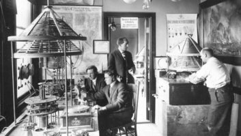
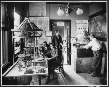
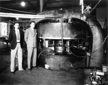
In the late 1920s, a race of sorts was underway on several shores to “split” the tiny atom in an effort to learn more about its internal workings. One of those heavily involved was the University of California’s Ernest O. Lawrence, future Nobel Laureate. He devised a tabletop model of a machine that could accelerate subatomic particles faster and faster until they had sufficient energy to pass through the electrostatic barrier of the atomic nucleus and send its constituents flying in all directions.
Once Lawrence, aided by a grad student, succeeded in making the tabletop nuclear particle accelerator — or “cyclotron” as Lawrence dubbed the device — work, the challenge was on to build a bigger and better model. (The cyclotron’s operation is based around a large magnetic field, just as in the arc converter.)
It so happened that once the vacuum tube had sunset activities at Federal Telegraph, there were some unsold arc converters literally rusting away at the company’s Palo Alto, Calif., facility. Lawrence learned of this from Leonard Fuller, chairman of the university’s EE department, and it was not difficult to secure one of the last of this breed of transmitter and relocate it to the Berkeley radiation research lab for just the cost of the move. There, it was stripped of the arc chamber, and the magnetic core became the heart of the first big cyclotron, known as the “27-incher,” the diameter of the magnetic poles formed from the big electromagnetic. This machine produced energies of 5,000,000 electron volts, and was later upgraded to give an 8 MeV push to deuterons, and it could also eject alpha particles at energies of up to 16 MeV.
Sidebar: The Physics of Arc Converter Operation
Aside from producing a continuous wave oscillation, an arc transmitter, or converter, is differentiated from a spark transmitter in a number of other ways. A spark machine can be powered from either an AC or DC source, while an arc device must have direct current. Spark transmitters utilize a fairly wide gap between the discharge electrode; those in an arc device are relatively close together.
Typically, both electrodes in a spark transmitter were made of the same metal (in many cases, tungsten), and while erosion does occur, the electrodes had a fairly long useful life. In an arc converter, the anode was almost always copper with a concave end, and the cathode was always graphite with a pointed end. Due to the very high currents involved, the cathodes had to be changed on a regular basis; typically, every few hours. The copper anode lasted longer, but had to be water-cooled, something not practical with the graphite electrode, which was rotated by a small motor during operation to equalize wear.
Another major difference between the spark and arc machines was the requirement for a strong magnetic field across the arc chamber and also a steady source of hydrogen during operation. As mentioned, this magnetic field was necessary for extinguishing or “blowing out” the arc during the RF oscillation cycle.
Hydrogen, the lightest and most mobile element, was used during these RF cycle “down times” to help clear the space between electrodes of residual ions generated by the intense arc plasma. The phenomena of arc “blowout” may be familiar to those who have done DC arc welding on, or close to, a steel structure. The arc plasma constitutes a conductor, and the magnetic field induced into the ferrous material tends to push the arc aside, sometimes making it tricky to control the weld.
Early in the evolution of the arc converter, the effect of the external magnetic field on arc performance was not well understood (leading to some major problems when it was desired to construct transmitters with increased power outputs). However, experimenters were aware that such a field greatly affected the performance and efficiency of the converter. One experimenter noted that without a magnetic field, the maximum RF current that could be delivered to the transmitting antenna was eight amps or so, but with the addition of the field, and everything else equal, an antenna current of 100 amps was easily obtainable.
Federal Telegraph’s Cyril Elwell, the American arc converter entrepreneur, was able for a while to build increasingly more powerful machines by simply scaling up the mechanical parameters (proportionally including the size of the arc electrodes, chamber, cooling system and electromagnetic field).
But he hit a major stumbling block when trying to go beyond 30 kW. This difficulty was not resolved until a young man with a recently-minted electrical engineering degree and a strong interest in arc technology, Leonard Fuller, was hired by Federal about the time that Elwell made a decision to exit the business. Fuller devoted much time in developing a sound physical understanding of what was really going on within an arc converter. (He eventually took Master’s and Ph.D. degrees based on his arc technology research.)
It was Fuller who realized that the intensity of the magnetic field needed for arc blowout was not directly proportional to the size of the machine or the desired output. He developed the concept of “tuning” the magnetic field strength to maximize output at a given operating frequency. With longer wavelengths there is more time available to clear the residual ions from the arc gap than at shorter wavelengths, thus a stronger magnetic flux is needed for higher frequency operation. (In the larger arc transmitters, magnetic fields upwards of 16 kilogauss [1.6 Tesla] were required. Most modern medical nuclear magnetic resonance imaging machines operate with a field strength in this range.)
Once Fuller understood fully the action of the magnetic flux, it became possible to design and build arc converters without any upper limit in operating power. Federal delivered a number of one megawatt machines, and plans were drawn up for two and five megawatt models, but due to the rapid pace of high-power vacuum tube transmitter technology, and the increasing relocation of long-distance radio communications from long wave to HF spectrum, these very high-power converters never made it into production.
Even though Federal rated its products in terms of DC power consumption, their 1,000,000-watt model produced about a half-megawatt of RF — still a very impressive number with antenna currents measured in hundreds of amps! The downside was the requirement to get rid of the other half megawatt of heat, which was usually solved by outside spray cooling ponds.
An Early Federal Telegraph Employee Describes His Experiences in Working for the Company
This article on arc converter technology was inspired by a 1963 oral history in which a former Federal Telegraph employee, Archie M. Stevens, was interviewed by Erwin Rasmussen, who captured some of early radio’s history from those still alive who had been a part of it.
The recorded audio interview (actually a two-part session with another pioneer, Ken Laird, and available online) begins with Stevens’ remembrance of the 1906 San Francisco earthquake while he was a student at nearby Stanford University. After earning an engineering degree from that school in 1909, Stevens was approached by one of his former instructors about a job with a startup company. As he recalled in the interview:
“Just about that time, I ran across Elwell, who had been my instructor in electrical engineering. He said ‘Why don’t you come with me? We’re starting a radio company down here called the Poulsen Wireless Telephone and Telegraph Company and we’ve got some very intelligent Danish engineers and machinists and a whole mix of stuff.’”
Stevens accepted the offer and rather quickly was assigned a position of responsibility in the fledgling enterprise.
“He made me chief draftsman and put me in charge of the machine shop,” said Stevens. “And then made me assistant engineer. That was a pretty big title, as I think we had 15 men all told.”
Stevens recalled that he was responsible for engineering drawings for both equipment manufactured and complete stations constructed with it. This included the massive towers used for the very low frequency antenna systems employed with Federal arc converters.
“I used to design the towers,” said Stevens. “In order to get the job done quickly, I would order the lumber and then take my drafting board out in the field and sit there and draw them [the towers], because we’d have to change the bolts and splices and that stuff [so much]. Elwood got the big contract for the 800-foot wooden towers in Rome. Mind you, people kept saying, ‘You can’t build wooden towers that are 600-feet high.’ [Well] we built them 800-feet high and they stood for 30 years. [We used] select first-quality pine from Oregon with 20 to 21 or 22 rings per inch. We made sure that it was kiln-dried lumber. That was the most important thing. Then we’d give them two or three coats of first-grade white lead paint… we put them together and we put in plenty of white lead.”
(Stevens recalled that at one station an airplane crashed into one of his towers and the tower withstood the impact, trapping the aircraft and saving its pilot from possible death if the plane had fallen all the way to the ground.)
In reflecting on the ever-present danger associated with using hydrogen and hydrogen-bearing compounds, Stevens recalled an episode when he was testing a new station installation, communicating with the operator of another arc station, and almost destroyed it the new facility.
“Sometimes we used pure hydrogen,” he said. “Well, I started out with pure hydrogen, but I didn’t blow enough air and set off a tremendous explosion which broke about a two-quart container of wood alcohol. I was alone at night and I went back and said I’m on fire; hold up a minute until I can get the fire out. I was scared that time.”
He also provided some insight on audio modulating the “fire-breathing” arc machines.
“The difficulty in modulating the arc was that you had this tremendous magnetic field with reluctance so big you couldn’t change it exactly as the voice of the speaker. So, the only way to do it was with what we called a closed oscillatory circuit with the arc and loosely coupled to an antenna — sometimes 10 or 15 feet away — with an inductance … you could modulate the current in the antenna, but you couldn’t modulate the arc itself. That’s how we used to telephone. We used to talk to Stockton and San Jose … but we had to stop the telephone [service] because there was no money in it.”
Interestingly, Stevens sheds some additional light on the large WWI-era communications facility planned for Monroe, N.C. and mentioned in my own April 19, 2017 Radio World Engineering Extra story about insulator manufacturer Arthur Austin.
According to Stevens, the station was to have been located much further north, possibly Maine, but Secretary of the Navy Josephus Daniels, a North Carolinian, insisted that the facility be constructed in his home state. Federal produced, but never delivered, the giant arc converters ordered, as the war ended before station construction could get under way. Stevens noted that one of these “war surplus” transmitters was given to Ernest Lawrence to be used as the foundation for the first large cyclotron.
The complete interview with Stevens and Laird is available online. Even though the audio quality is less than perfect, provides much insight into what it was like to work for Federal Telegraph and the pre-vacuum tube era of radio in general.
FURTHER READING
Adams, Mike and Greb, Gordon B., “Charles Herrold, Inventor of Radio Broadcasting,” McFarland, Jefferson, N.C., 2003.
Aitken, Hugh G. J., “The Continuous Wave: Technology and American Radio, 1900-1932,” 1985, Princeton University Press, Princeton, N.J.
Boucheron, Pierre H., “Arc Undampt Transmission,” Radio Amateur News, Oct. 1919
Byron, William J., “The Arc Method of Producing Continuous Waves,” The AWA Review, Vol. 7, 1992, The Antique Wireless Association, Bloomfield, N.Y.
Davis, Nuel Pharr, “Lawrence & Oppenheimer,” 1968, Simon and Schuster, New York
Fuller, L. F., “The Design of Poulsen Arc Converters for Radio Telegraphy,” Proceedings of the IRE, Vol. 7, No. 1
Secor, H. Winfield, “Construction of a Collin’s Radiophone Arc,” The Electrical Experimenter, Feb. 1916
Stone, Ellery W., Lieutenant USNRF, “The Poulsen Arc,” United States Naval Proceedings, Vol. 46, No. 2, July 1920; U.S. Navy Institute, Annapolis, Md.