Much has been written about the program, performers and setting of KDKA’s “big broadcast” of Nov. 2, 1920, including our recent story “Radio Broadcasting Becomes a Reality,” but precious little is documented about the technical aspects of the equipment package that made it possible.
With the aid of detailed photographs; magazine articles about the station and its progenitor Frank Conrad; and a published account by an eye/ear-witness to what transpired, it’s possible to piece together many of the missing details.
Perhaps most useful is a 1955 American Heritage article by Donald Little, a Westinghouse engineer who helped to construct that first KDKA transmitter.
“During the fall of 1920, Dr. Conrad had me design and help the model shop at the works build the transmitter. The transmitter had a power of about 100 watts. They built a room on the roof of one of the taller buildings at the East Pittsburgh works and put up an antenna and counterpoise from a steel pole on that building over to one of the powerhouse smokestacks. The antenna and transmitter were completed only a few days before the presidential election of November 2, 1920.”
The association between Little and Conrad extended back some three years when Little, who had been working for what was then called the National Bureau of Standards (now the Institute of Standards and Technology) was dispatched from Washington to East Pittsburgh to oversee the development and production of transmitters and receivers by Westinghouse for the U.S. Signal Corps.
(While Little consistently refers back to “Dr. Conrad,” it was not until 1928 that the University of Pittsburgh bestowed an honorary doctor of science degree upon Conrad.)
THE TRANSMITTER
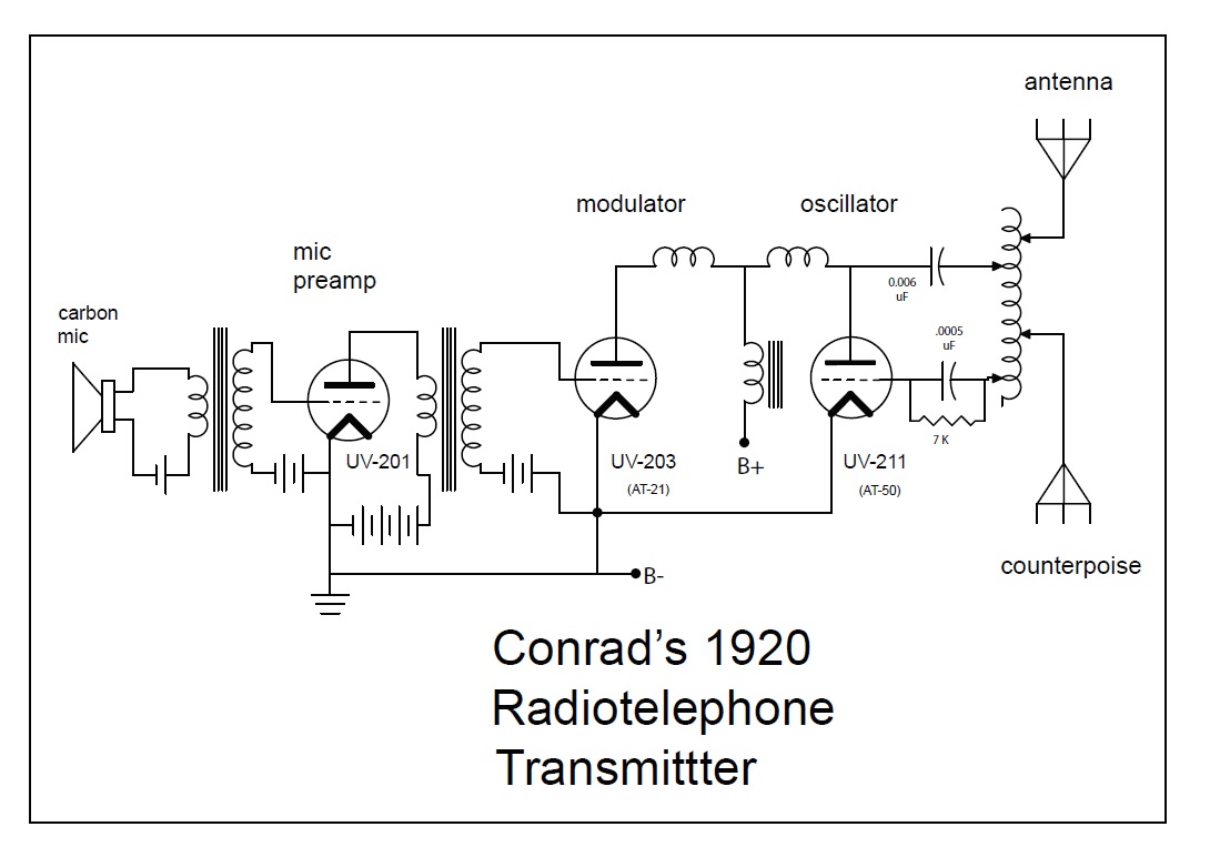
No schematic diagram or construction details of the Westinghouse “broadcast” transmitter exist. Based on the “state of the art” at the time, coupled with knowledge of the radiotelephone rig constructed by Conrad for his ham station, it doubtless employed the “constant current” system of modulation developed earlier by Western Electric’s Raymond Heising.
The radiotelephone transmitter Conrad constructed for his amateur radio station is documented in a Sept. 1920 article in amateur radio publication, QST. It’s believed that the one constructed at Westinghouse was more or less a scaled-up version (100 Watts output versus the 50 stated for the ham station rig).
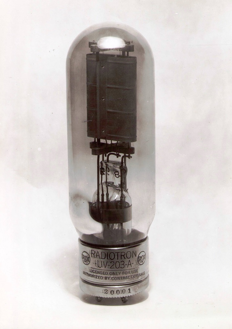
Conrad (and Little) would have employed state-of-the-art power triodes developed by General Electric and manufactured by Westinghouse’s “lamp works” during the First World War, when patent and licensing issues had been temporarily tossed aside to ensure a plentiful supply of “strategic materials.”
Lud Sibley, a vacuum tube expert and editor of the publication Tube Collector, opines that the power oscillator was likely “the humble AT-50, Westinghouse’s production of GE’s UV-211.”
Sibley also believes that Westinghouse’s AT-21 (equivalent to a GE UV-203A) could have served admirably as the modulator.
If these tubes were used in paralleled configurations, the transmitter could have easily delivered 100 Watts of modulated RF.
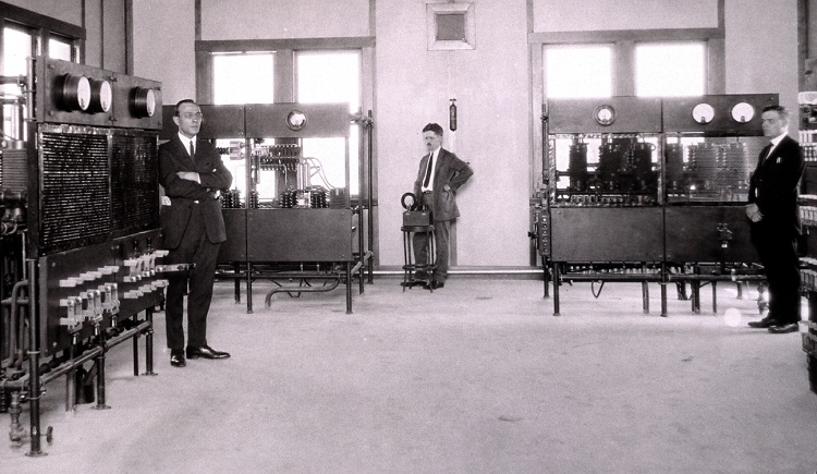
It appears from one of the surviving pictures of the rig that filaments may have been heated with pure DC from an automobile storage battery. (It’s likely that the battery was continuously “float charged” to ensure that the heavy filament current drain didn’t deplete it before the broadcast ended.) Three “brick” type dry cell batteries are visible behind the transmitter and just to the right of the six-Volt storage battery. These could have served as a source of bias voltage for the triodes, and due to the size and number, also as a plate voltage for the transmitter’s “speech amplifier” (audio input stage),
The picture of the radio room, sans people, also sheds some light on the high voltage supply for the power tube anodes.
Immediately to the right of the transmitter panel board, a heavy-duty pushbutton switch is visible. It’s safe to assume that this controlled a motor-generator set located remotely so that its very audible operating noise didn’t get transmitted along with the election commentary. (Later, Westinghouse manufactured a line of motor-generators for broadcast transmitter applications, as I described in my 2011 Radio World article “How Transmitter Power Supplies Evolved.”)
A more comprehensive description of the KDKA transmitting antenna — at least as it existed less than two years after the 1920 broadcast — was offered by Little in a 1922 article in Radio News about the station’s technical facilities:
“[It consists of six wires] 90 feet in length on 20 foot spreaders. This antenna is supported 210 feet above the ground by a brick smoke stack at one end and by a 100-foot pipe mast on a nine-story building at the other end. A counterpoise [elevated radial] which is a duplicate of the antenna in construction is placed 110 feet beneath the antenna. The down lead from the antenna and the counterpoise lead are made up of eight strands of No. 14 copper wire equally placed around 1.5 in. diameter wooden spacers. The natural period of this aerial system is approximately 412 meters. A condenser … in series with the antenna and sufficient loading inductance [was] added to obtain the desired wave length of 360 meters.”
Conrad used a similar antenna/counterpoise system at his ham station.
The microphone was essentially a telephone “transmitter” (carbon mic) backed up by the necessary battery and a one-stage triode pre-amplifier, most likely the newly developed UX-201, which later, along with a lower filament current version, the UX-201A, became the tube of choice for many 1920s commercial and homebrew receivers.
PROTOTYPE BROADCAST “TURNTABLE”?
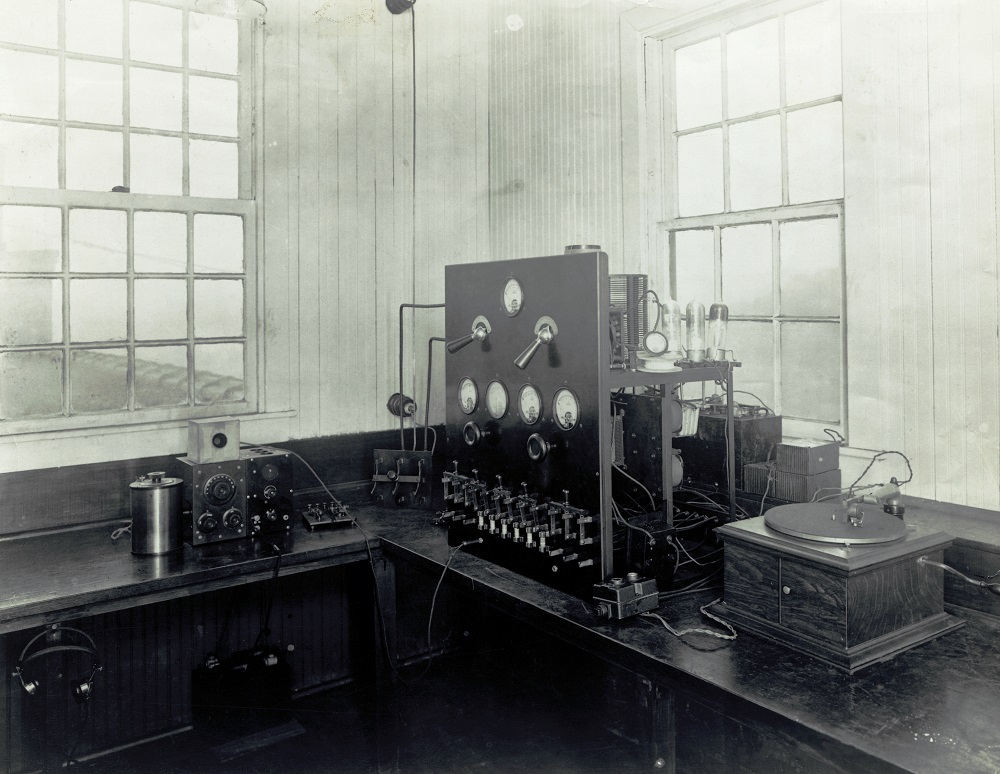
The transmitter room picture does present something of a mystery.
A windup phonograph was used as a source of “fill” music so there would be no dead air when announcer Rosenberg was waiting for election results to be updated; in the photo from that night it can be seen to the right of the transmitter panel, its crank visible next to John Frazier as seen in Fig. 4.
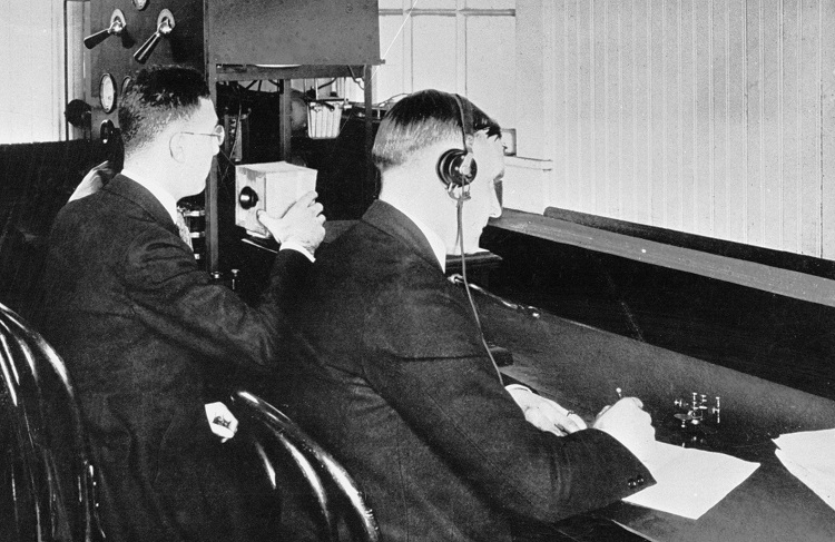
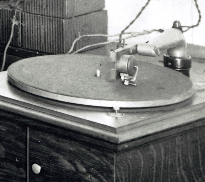
What makes this otherwise nondescript record player interesting is a length of “twisted-pair” lamp cord that connected the transmitter to an object (electrical phonograph pickup?) attached to the “arm” on the phono. The cord is visible in Fig. 5.
History tells us that the first electrically recorded records (and electrical pickups for reproducing them) didn’t appear until 1925, stemming from research at Western Electric and Bell Labs.
Did Conrad and Little somehow jump the gun and invent an electrical pickup half a decade before Bell?
In his 1955 writing about the 1920 inaugural broadcast, Little seems to clear up this mystery:
“It was thought that election news would not occupy the whole time so a hand-wound, spring-driven phonograph and a selection of records were provided for fill-in purposes. I arrived at the station about 6 P.M. the night of November 2, 1920, in plenty of time to be sure all would be in readiness to start the program at, as I remember it, 8 P.M. To my dismay, I found that the gooseneck of the phonograph tone arm had disappeared. It was never found and to this day I do not know whether it was maliciously stolen or simply mislaid accidently. It was obviously up to me to provide some sort of substitute which I did by rushing down to our laboratory and putting together a clamp and hinge gadget that hinged the microphone to the tone arm. It was quite satisfactory and was used for the opening program and several later ones.”
What Little cobbled up that evening may have been much more complex, however.
A careful examination of a blowup of the phono portion of the photo indicates that Little may have manufactured a true “electrical” pickup.
Clearly visible is an “outrigger” bar with a clamp for the microphone that has been attached to the phono horn’s acoustic coupling “stub,” with the “stub” only serving to support Little’s contrivance above the record grooves and allow it to track across the record.
Seen at the bottom of the device are a chuck and a thumbscrew for holding the “needle” (stylus). Quite prominent in the photo is a “U”-shaped rod that appears to be used for coupling needle movement to the microphone element.
I don’t claim expertise on early mechanical (acoustic) phonographs, but the conventional “diaphragm” that was coupled to the needle and translated needle movement to sound pressure waves “amplified” by the phono’s horn (actually an acoustic transformer) is not visible in this photo.
I shared the photo with a restorer and conservator of early recording and reproduction apparatus. He said, “I’ve never seen anything like this.”
If the device that Little fabricated was really a carbon mic driven directly by the needle, the audio reproduction of the recordings would have been considerably better than that achieved previously by just placing the mic in front of the phono horn. (It would have also prevented pickup of conversations and other background noise in the radio room while the records were played.)
I leave it to others to decide exactly what did or didn’t happen in this respect.
The author thanks Rick Harris, chairman of the Conrad Project at the National Museum of Broadcasting, for his help with this article.
[Related: “What, Exactly, Was ‘First’ About KDKA?”]