The history of audio processors for U.S. radio stations can be roughly divided into two chapters. The first, when these devices were a compliance tool for FCC regulations regarding transmitter modulation. Their job was to maintain average modulation levels between the required 85 and 100%, and ensure audio peaks never exceeded 100%. The second chapter, after the loudness wars began, when audio processors were used to create a signature sound for a station, and ensure modulation levels were kept as high as legally possible.
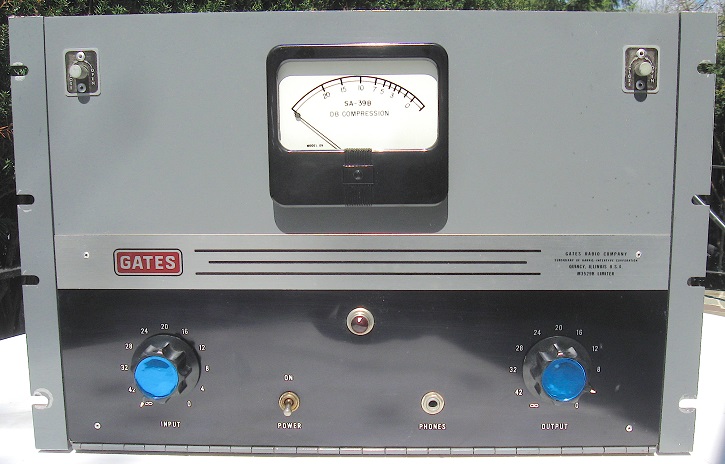
The Gates Sta-Level AGC and SA-39B peak limiter belong to the earlier era.
Both were introduced in the 1950s, and enjoyed long service lives. They were designed around conventional textbook circuits with no “black boxes” or deep secrets about how they operated. Both were easy to set up and maintain. They were marketed by Gates throughout the 1960s and early ’70s as the perfect pair for maximum modulation.
Simple Setup
The SA-39B was introduced by Gates in 1957, and replaced the similar SA-38, which was designed in 1948. It was marketed as a solution for AM, FM and TV operations.
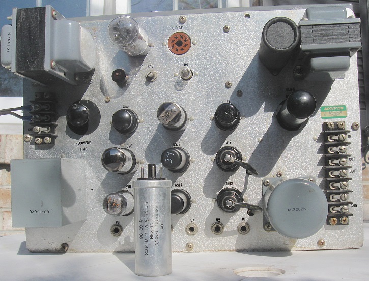
The SA-39B’s audio circuit consisted of three push-pull stages: 1612, input; 6SJ7, intermediate; and 6V6, output. The regulated power supply had a 5V4 rectifier, and 6X5, 6SJ7 and 6L6 in the regulator circuit. A 6H6 functioned as the control rectifier. This regulated supply powered the first two audio stages. To ensure low noise, the filaments of the 1612s were run off a separate DC supply.
The theory of operation is simple. The audio output signal is sampled, rectified by the 6H6, and the resulting negative voltage connected to the second control grids of the 1612 input stage. As the output voltage increases, the grid becomes more negative, lowering the gain of the amplifier. Through compression levels up to 20 dB, distortion remained at a respectable 0.05% or less.
Compared to today’s audio processors, there were few adjustments and options to consider when setting up the SA-39B. Attack time was fixed at 0.001 seconds. Release time was adjustable via a six-position switch on the rear panel. Position 1 had a recovery time of 0.2 seconds, and each successive position added an additional 0.2 seconds. Position 3, with 0.6 seconds was the recommended starting point, and could be adjusted faster or slower to suit the format.
A tweak inside the limiter was used to set the front panel meter for 0 dB compression with no input. Then, it was simply a matter of increasing audio input until normal programming showed about 5 dB of compression. This setting allowed sufficient headroom for the occasional intense peak energy.
Output levels could be adjusted to +20 dB. If that was too much, two fixed attenuator pads could easily be inserted into the circuit.
[Read more tech history: Proof of Performance, 1970s Style]
A nice feature of the SA-39B was the six 1/4-inch phone jacks on the bottom of the rear panel which were wired to measure cathode current of the audio stage tubes. With a 1/4-inch phone-to-banana plug patch cable, it was a simple matter to check these currents with a VTVM. Normal currents for each stage were indicated on the schematic.
There were two reasons for regular checks. Cathode current is a good indicator of tube life and when it begins to fall, the end is near. Second, push-pull circuits only work well when the tubes are balanced, and tubes don’t always age at the same rate. Imbalance can lead to increased hum and distortion, and in the case of the 1612s, thumping during low frequency passages.
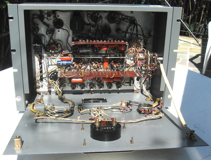
Maintenance was fairly simple, with the usual tube checks and logging socket voltages. Access via the drop-down front panel gave access to most of the resistors and capacitors, neatly laid out on two circuit boards. Earlier tech manuals for the SA-39B documented component designations, values and voltages, but that went away when the abbreviated four-page manual was released.
A nice feature of the SA-39B was the 20-20 µf 450 volt power supply electrolytic, which was provided on an octal socket. These capacitors were more expensive than the conventional twist-lock style, but made replacement a plug-and-play procedure, rather than a tedious and time-consuming chore.
The Gates SA-39B, and comparable peak limiters such as the RCA BA-6C and Collins 26U-1 were among the first casualties of the loudness wars. When the FCC passed regulations allowing AM stations to increase their positive peak modulation from 100 to 125%, their days were numbered. Asymmetrical modulation called for entirely different circuits for peak limiting. By the mid 1970s, the loudness wars had spread to the FM front. When the Orban Optimod 8000 was introduced around 1976, it revolutionized FM audio processing, and conventional peak limiters began to disappear there as well.
Cult Status
While the SA-39B has largely faded from memory, the Gates Sta-Level has been elevated to cult status as the decades have passed. In fact, software-based audio processors often have a “Sta-Level” setting to emulate its unique sound.
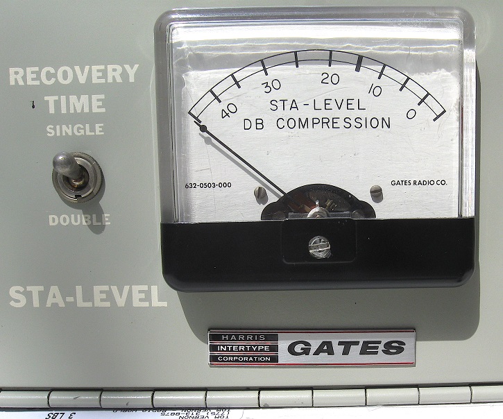
Introduced in 1956, the Sta-Level was in the Gates product line for the next two decades. It had a well-deserved reputation for its unobtrusive control of audio levels. The secret was the GE 6386, a remote-cutoff twin triode. It had a long life, and never seemed to lose its wonderful linearity. A little-known fact is that the Sta-Level was not the first audio processor to use the 6386.
Shortly after General Electric introduced the 6386 tube, its broadcast products division introduced the 4BA9B1 Uni-Level to take advantage of it. The Uni-Level was a stripped-down AGC amp built for a low price-point. Input and output levels were controlled by fixed resistive pads, there was no compression level meter, and minimum parts count. The tube lineup was a 5Y3 rectifier, 6386 push-pull input/control, 6AL5 control rectifier, and (2) 6V6 push-pull output. They started selling like hot cakes.
Gates wanted a piece of the action, but they didn’t want to run afoul of GE’s application patent on the Uni-Level circuit. The challenge for Gates engineers was to design a device that utilized the 6386, but was sufficiently different to dodge a patent infringement. They did this by putting an OB2 regulator for the 6386 plate supply as well as adding a 12AT7 between the 6386 variable-mu stage and the 6V6 output stage. It was totally superfluous, and all the extra gain was swamped out by negative feedback. But it did keep the lawyers happy.
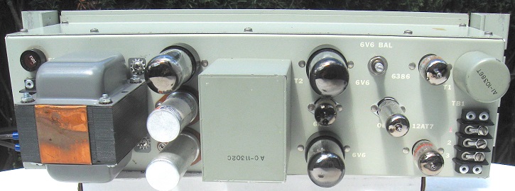
One of the underground mods for the Sta-Level was to remove that 12AT7 and couple the plates directly to the 6V6 grids with 0.5 µf mylar capacitors. The result, less noise distortion and heat, better sound. But many engineers didn’t stop there.
Back when stations used to build their own equipment, the Sta-Level’s schematic was the jumping off point for far more elaborate devices. Precision resistors, high-quality audio transformers, audio attenuators and other high-end components were often used.
While the Sta-Level used an OB2 to regulate power to the 6386, many home-brew designs regulated everything, often using a 6AS7 with a 6SJ7 DC amplifier and OB2 VR tube as a reference.
Some stations went all out with the metering circuit, adding a rotary or pushbutton switch to select dB compression, audio output VU, cathode current of the audio stages, DC filament voltage for the 6386 and balance of the two push-pull stages. A few circuits also included indicator bulbs for expansion, compression and when the gain was frozen. They were not terribly useful, but fun to watch.
[Read more fun radio history from Tom Vernon: The Time Has Come to Talk of Many Things]
TV stations often had problems with the quiet passages in films, when the AGC would suck up all the background noise up to program level. The solution was to modify the Sta-Level circuit with a pot to control the DC bias on the cathode of the 6386. That would establish a platform which would limit the range overs which expansion would occur.
Setup and maintenance of the Sta-Level was straightforward. Once it was connected to the console output and being fed normal program level, adjust the input level control till the meter indicates around 15 dB of compression. Adjust the output control to properly feed the following device. At many stations, this was the phone line connecting the studio to transmitter, where the peak limiter was presumably located. Finally, set the recovery time for single or double.
As shipped, the Sta-Level’s recovery time for 2/3 level was 7 seconds, and 90% level in about 28 seconds. By changing the values of R36 and 37, that could be increased to as fast as 2.25 seconds for 2/3 level and 10 seconds for 90% level. This was a common mod for top 40 stations. Want to slow it down instead? Then 11.25 seconds for 2/3 level and 45 seconds for 90% might be more to your liking if you had an easy listening format.
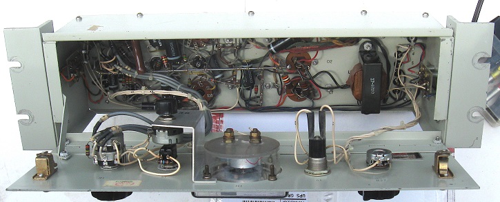
Sta-Level had a tweak for balancing the cathodes of the 6V6 output stage. The manual called for matching the voltages, but a more precise method was to adjust for minimum distortion at 1 kHz. That was about it for adjustments.
Due to its simple design, reliability and great sound, the Sta-Level was used lots of places besides the air chain. If you purchased a Gates automation system in the 1960s or ’70s, it often had a pair of Sta-Levels on the audio output to even out the levels between different sources. Stations used them in production room for the same reason. Some were wired into a patch panel so they could be deployed for sports remotes, which had notoriously erratic levels. Talk stations were known to use them on phone lines.
While both units enjoyed a long service life, advancing technology eventually caught up with them. In 1975, Gates/Harris introduced the Solid Statesman line of audio processors. This included the M-6543 AM limiting amplifier, M-6631 FM limiting amplifier and M-6629 automatic gain control amplifier.
The Sta-Level and SA-39 pictured with this article were found while cleaning out transmitter buildings during the contract engineering days of the 1980s. The SA-39 dates from the late 1950s, while the Sta-Level was manufactured in 1967. They were cleaned up and returned to good operating condition. Both are now enjoying their retirement as objects of affection in my own personal home museum of oddities.