Remember Kenneth Lundgren’s unidentified audio transformer, discussed earlier and pictured here? There was no identification marking, so Kenneth invited thoughts from our readers about the type of transformer.
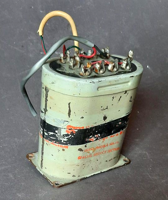
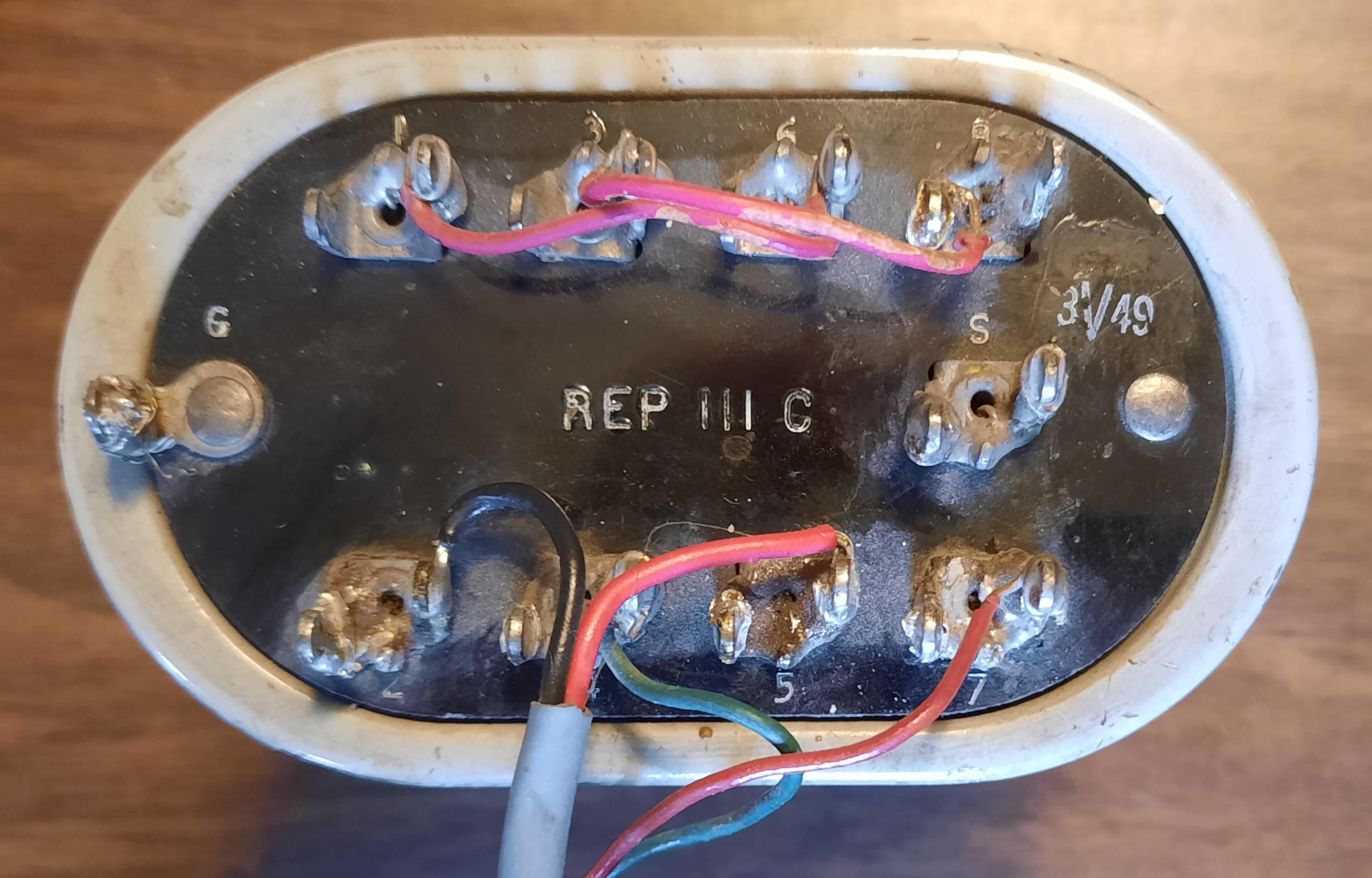
Rocket Engineering Principal Rolf Taylor believed the answer to Ken’s question might be in not-so-plain sight. Rolf recalled that in addition to the printed nomenclature on the side, there should be an inscription “REP 111C” embossed into the insulator on the top. Online pictures confirmed this. So Rolf suggested that a quick flush with contact cleaner might solve the mystery.
Before I could pass on Rolf’s suggestion, Kenneth emailed to say that he had indeed cleaned off years of crud from the insulated top and sure enough found the embossed legend as shown here.
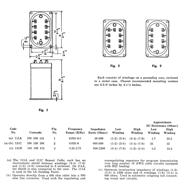
Ham and broadcast engineer Sheldon Daitch sent us an information sheet from 1980 that describes the variety of AT&T repeat coils or audio transformers. The more common models are 111C versions, but others exist as seen in the accompanying image, which depicts 111A and D models as well as C type.
(If you’d like a PDF of that image with better resolution, just email me at [email protected].)
Even the BBC used these
Dave Porter is a retired BBC senior transmitter engineer. He tells us that the BBC used similar transformers connecting the studio and transmitter site.
They’re known in the U.K. as REP coils, short for repeating coils. Dave writes that the BCC designed many of these models in-house. What made them and the Western Electric versions so popular was their four windings that could be connected to give a 600-to-600 transfer, a 150-to-600 transfer or a 150-to-150 transfer by series / parallel combinations of the terminals on top.
On the 250 kW Marconi BD272 HF transmitter used in the mid-1960s, an RF demodulator was provided using a sniff of RF from the final RF stage. An EY84 (US 6374) tube was used as the diode, rated to 625V RMS at 125 mA! The output was to a 600/600 rep coil to provide an audio feed.
Physically, the BBC version was an 8-inch cube. There was certainly no danger of the usual zero level, 0 dB (0.775V into 600 ohms) at 40% mod and the +8 dB on program to 100% modulation overloading that component!
First do this, THEN do that
After reading our column in April about maintaining your AM antenna tuning unit, broadcast engineer Paul Sagi in Malaysia sent a reminder.
Before shorting a tower to ground, consider discharging with a high-voltage discharge stick so that when you do the shorting, there will be less of an arc, or none.
When shorting, be sure to connect the ground end of the shorting cable before you connect the tower end. If you connect the tower end first (especially if you did not first use the discharge stick), your body may become the short to ground! That tall tower may be absorbing RF from other adjacent towers.
Be careful around high voltages. There are no second chances or do-overs. They can kill a person instantly, even if the current is fairly low.
Hey, do you like your shrink?
We wrote earlier about heat shrink including 4-to-1 shrink and printable shrink (Brother makes a great shrink printer).
Mike Pappas is VP for business development at Orban Labs. He recommends adhesive-lined shrink tubing, saying it is handy for outdoor use or things like F connectors, which tend to disassemble themselves with repeated use just when you need them the most.
They take longer to shrink because you have to heat up the adhesive with your heat gun, but properly applied, they provide robust weatherproof junctions and serious mechanical stiffening.
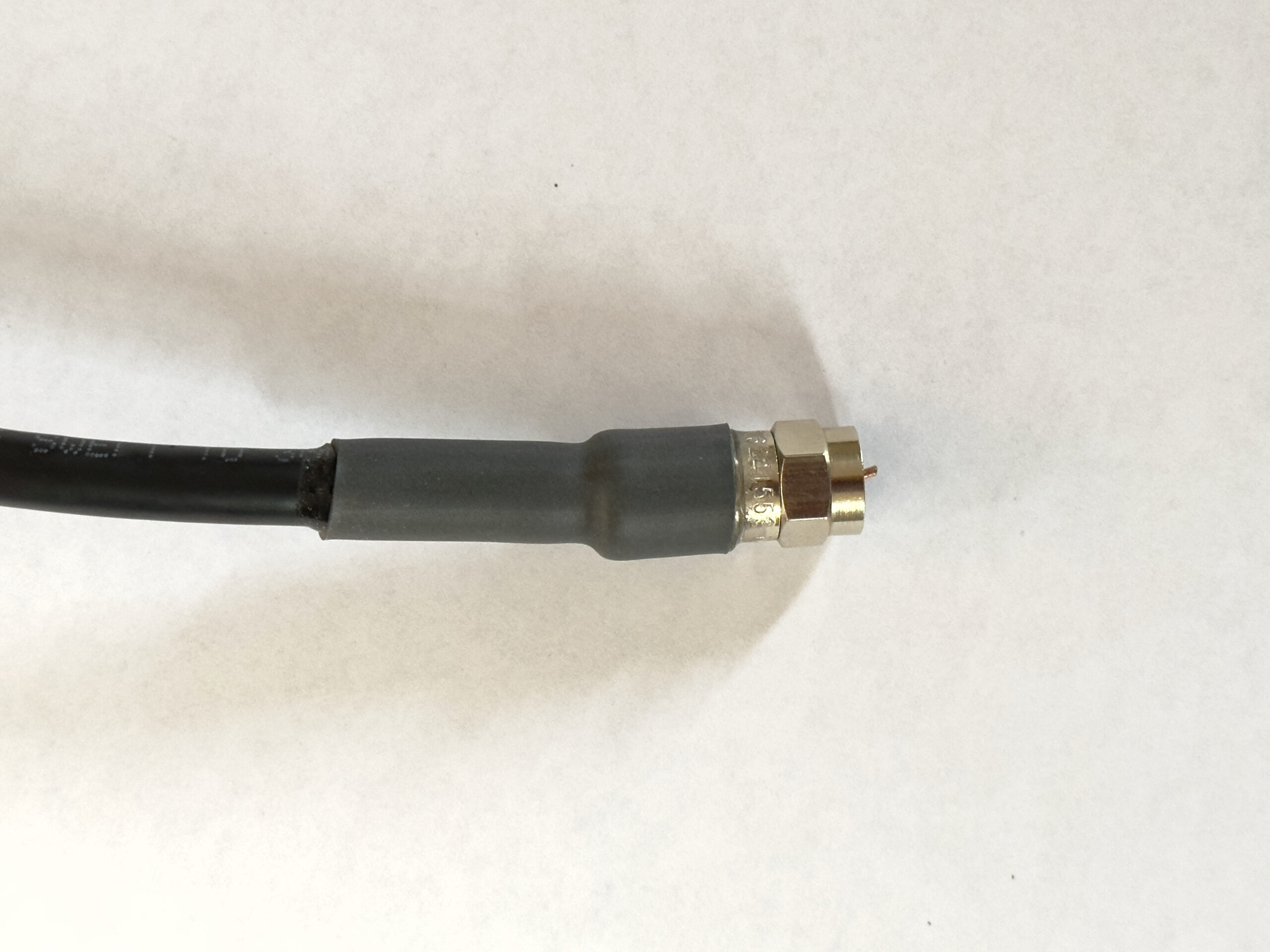
Note that adhesive-based shrink is notoriously difficult to impossible to remove. User beware.
Mike sources his shrink from Digi-Key Electronics, which has a myriad of it in all kinds of sizes and configurations. At this writing they listed 15,000 SKUs.
The final image here shows a compression F connector with adhesive lined shrink on it. You can see the adhesive “beads” on each end of the shrink. That connector is now weatherproof and it’s never coming apart.
You can be a transformer too! Your tips for Workbench will help a colleague become a better and smarter engineer. Email [email protected].