In Part 1 of this series on audio fundamentals (“Let’s Talk About Some Basics of Audio for Radio”), we discussed audio problems and how to handle audio transformers.
Most of today’s studios don’t need transformers to couple audio from one place to another. Integrated circuits (ICs) with operational amplifiers made a huge improvement in audio quality starting in the early 1980s.
Our discussion today is mostly about analog audio, though some techniques apply when connecting analog audio to digital devices.
Active balanced
Inexpensive ICs can send and receive audio on balanced lines. That means a pair of wires, isolated from ground, carrying analog audio. We call it “active balanced.”
With balancing, each of the two wires has audio, but they are 180 degrees out of phase from each other. To keep things straight, we label one wire as “+” while the other is “–”. This is important in stereo, where an accidental reverse of the wiring could cancel monaural material.
Fig. 1 shows a dual trace oscilloscope displaying a 1 kHz tone. The top trace shows the + wire while the bottom trace shows the – wire. One is going positive in audio voltage while the other is going negative. That doubles the voltage delivered and multiplies the power by four.
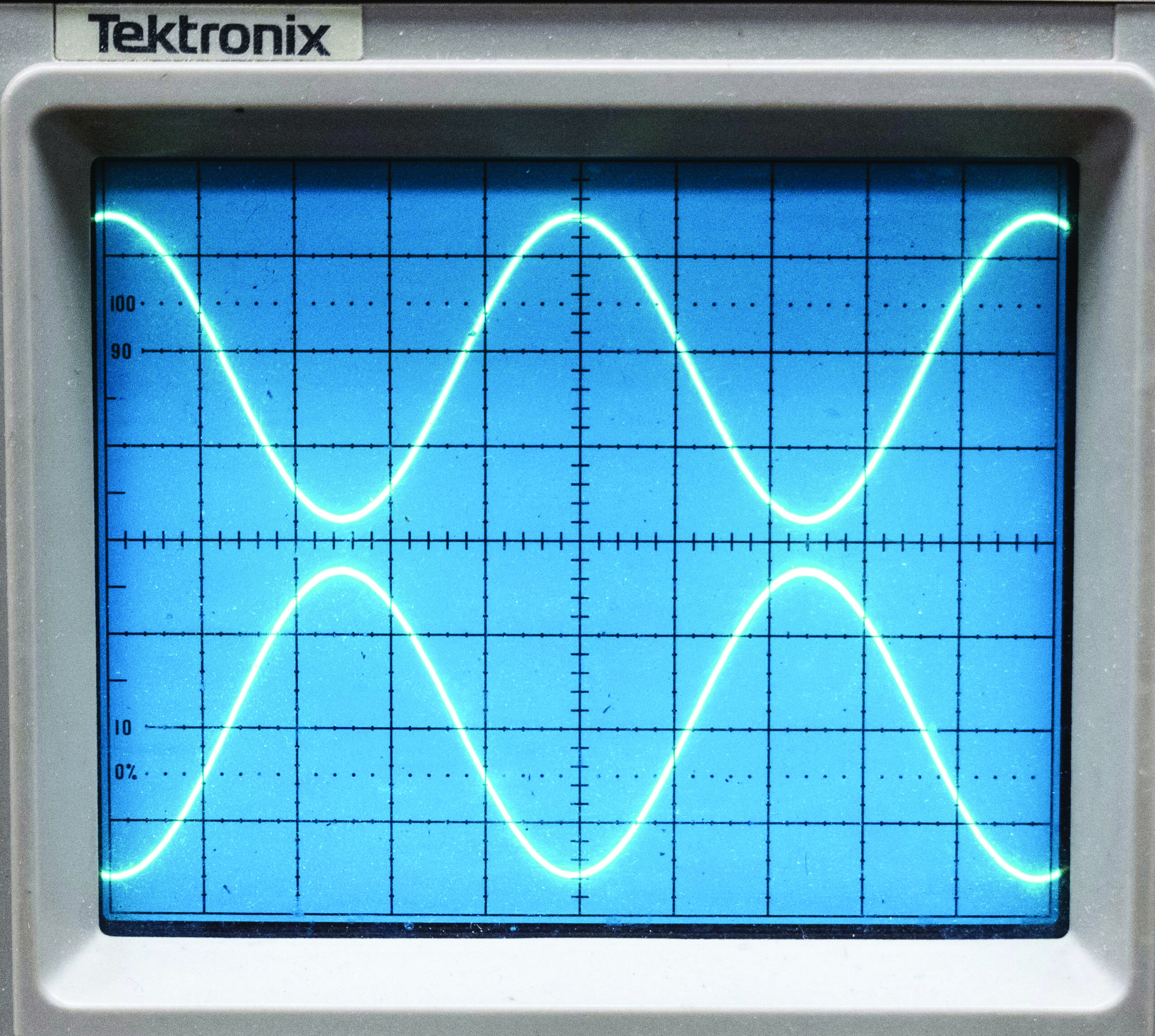
Power isn’t a big concern because we are talking fractions of a watt, but it helps keep a high audio signal-to-noise ratio. We don’t want to hear hum and noise in the background of the air product.
Fig. 2 shows an active balanced audio output driving an active balanced input. A typical source impedance is 50 to 600 ohms while the receiving end is typically 10,000 ohms. Audio is, in essence, sampled without loading down the source. Audio can be sent to multiple destinations in a building without degradation. Note there is no reference to ground. There doesn’t need to be if all audio devices are grounded through their power cords.
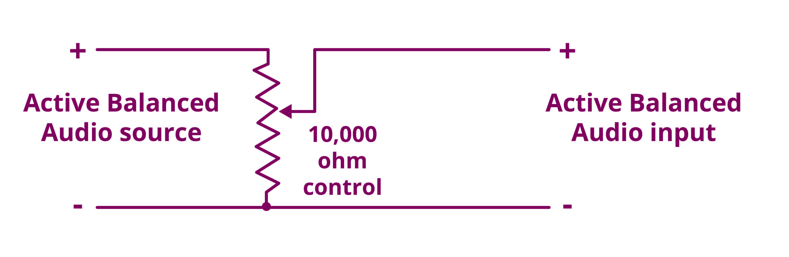
Also shown is a 10,000-ohm variable resistor to adjust audio level. If adjusting is not necessary, remove the control and connect + to +. The diagram is for one audio channel. You’ll want to do the same for the other channel to keep left and right stereo consistent.
Fig. 3 has an unbalanced audio device, such as a CD player that has a two-wire power cord. The audio cable will have a phono plug at the CD player. That audio cable shield needs to go to the (–) input on the console. You should also connect the shield to console case ground. Connecting a shield to only the audio console (–) input might be a bad idea. Static electricity on the CD player could damage the audio console’s active balanced input amplifier. The schematic diagram shows loops around the + audio wire. Those signify a cable shield around that conductor, as required when handling unbalanced audio.
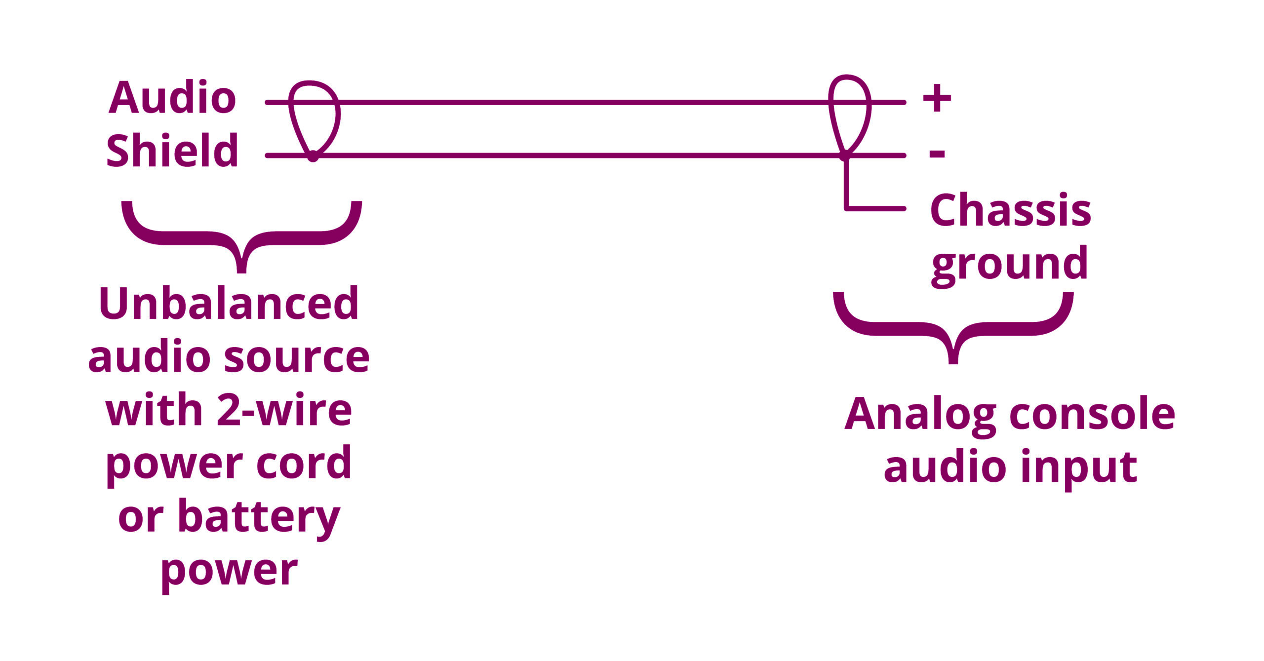
Fig. 4 shows an older Arrakis analog audio console’s input terminals. A #12 bare copper ground wire is held in place by solder lugs, which are screwed to the console’s metal cabinet. Call it a “ground buss.” The console did not come that way. I modified it to this configuration to keep the audio clean.
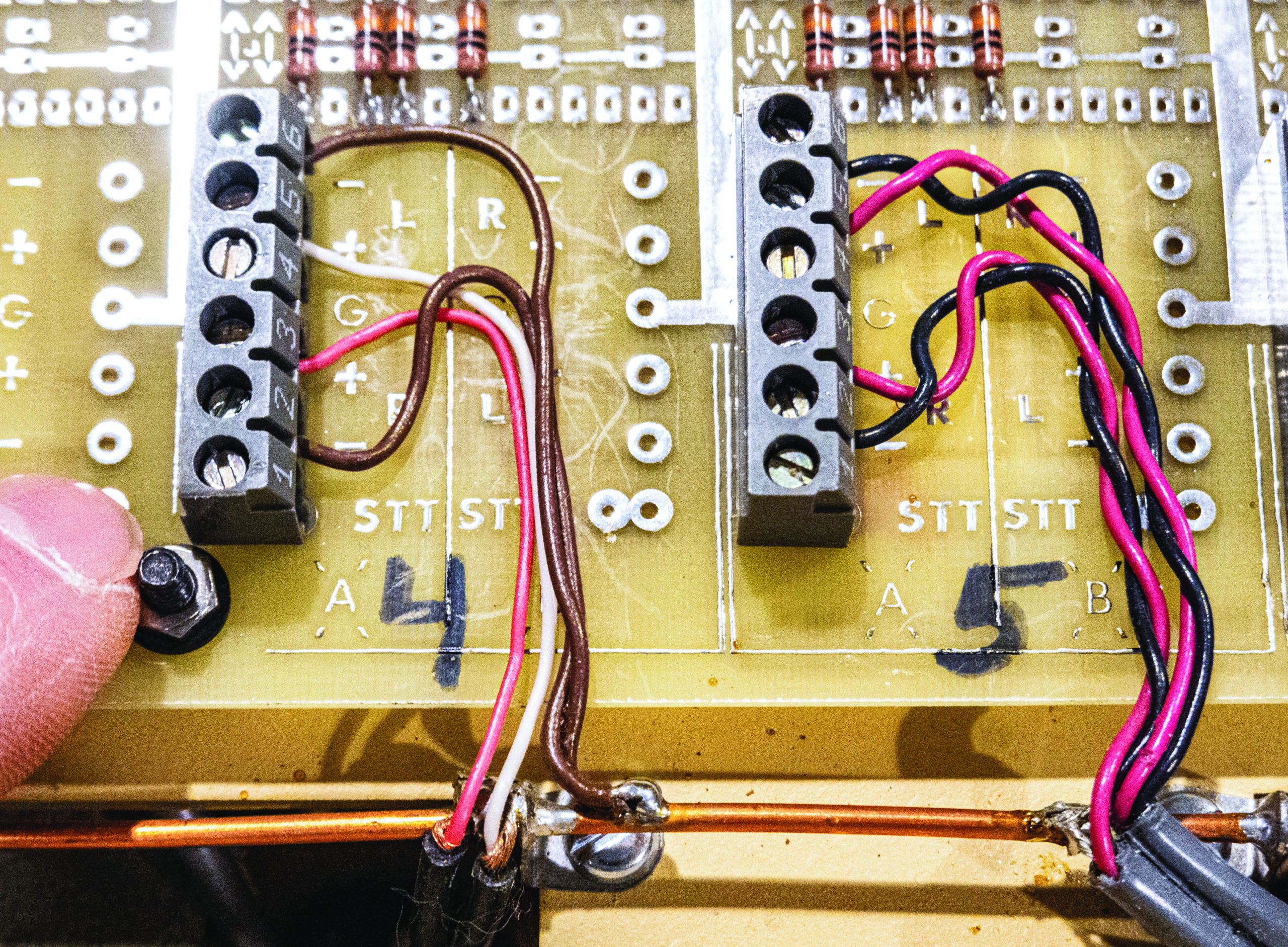
Note that cable shields tie or are soldered to the buss wire as opposed to connecting to the G (ground) input on the console’s circuit card. The reasoning is that there could be some AC leakage current flowing through the shield that might add hum or noise to the console audio by way of the console’s thin circuit board conductors leading to console ground.
Best to connect all shields to the metal console cabinet, as shown here. I worry a bit about putting a static electric shock into an audio console when an audio source is connected or disconnected from power. Connecting the shield to console case ground should keep this problem at bay.
The internal console electronics typically tie to the buss over at the output amplifier board with just one wire. It is a bad idea to run multiple grounds to multiple circuit cards. All console circuits need to seek ground at one point to keep audio clean. That is usually at the output card.
This console’s #4 input has stereo unbalanced shielded cables from a CD player. They are the red and white wires going to the L+ and R+ inputs. Their shields go to the ground buss. The active balanced L– and R– inputs are tied to the ground buss via the brown wires. This is the best way to do it.
Console channel #5 is receiving audio from an active balanced source. The source cable shields are tied to the ground buss, not to the G as indicated earlier.
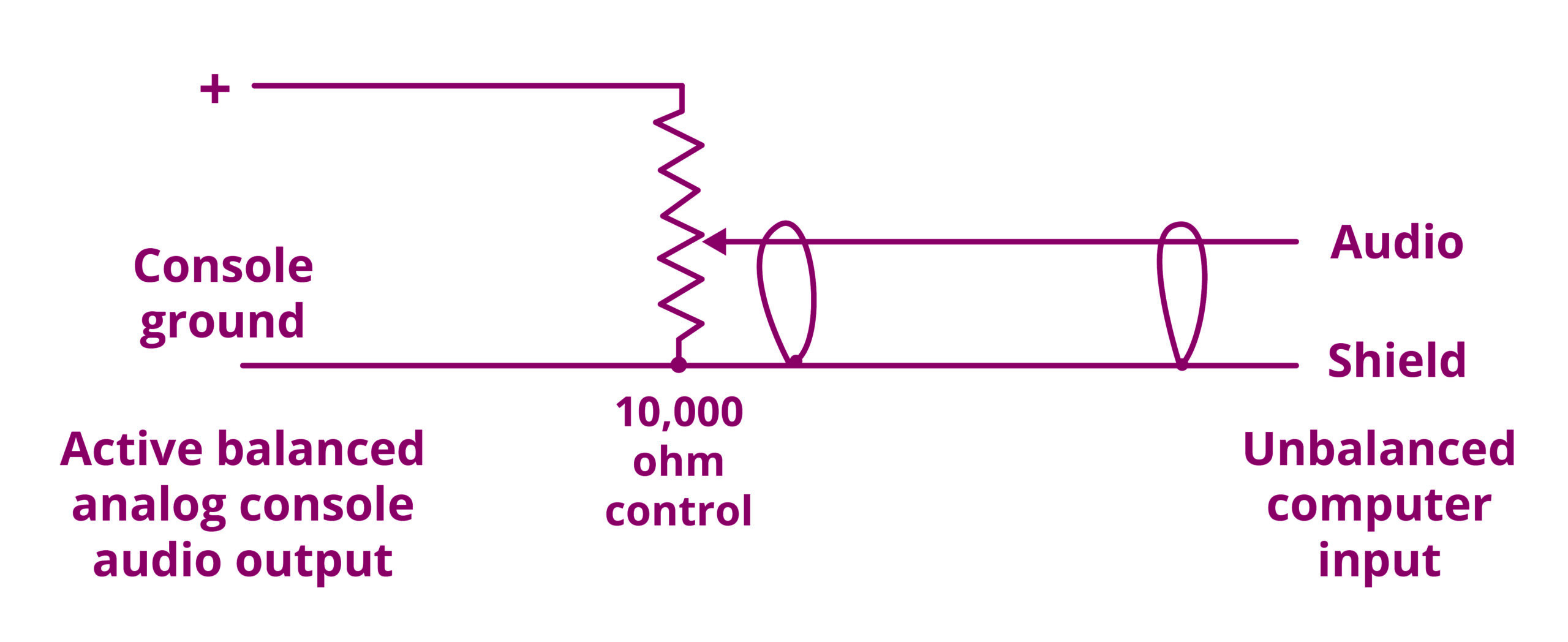
Feeding audio to an unbalanced device, such as a computer, has its challenges. See. Fig. 5. Use either the + or – output of the audio console along with the buss ground, not the ground terminal on the console’s output connector. As with the console’s input, seeking ground through a circuit card trace can lead to adding noise to audio.
With console outputs ranging from 0 dBm to +4 dBm, there is likely more audio than needed when sending audio to a recording device. Fortunately, audio from just the + or – output of the console is 6 dB less than the total of + and –. This may still be too much for a recorder. Fig. 5 shows a 10,000-ohm variable resistor to set level.
Equipment with a three-wire power cord is already grounded via the third pin on a power plug. This kind of situation is not always predictable. Start by using an audio cable shield to connect grounds at each of the two devices that have grounded power. Hum and noise might result. You’ll likely wind up disconnecting the ground at one end. You might use a heavy wire to bond the console ground to the computer case. Use an audio transformer only if necessary.
Safety
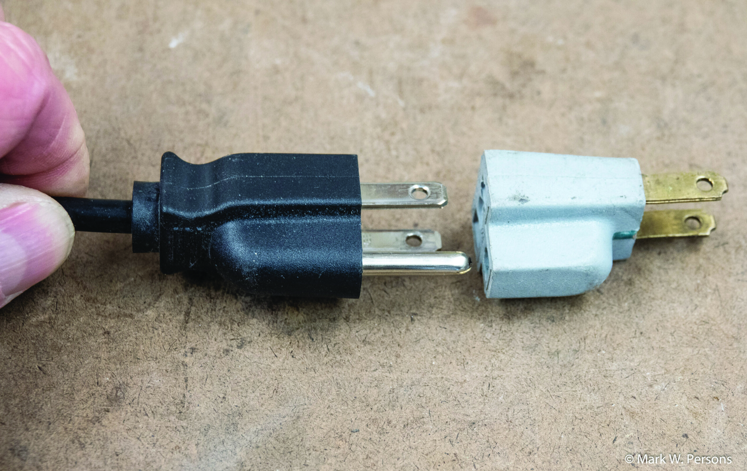
An audio hum problem can be made to go away when a ground adapter is connected in series with a three-wire power plug, as seen in Fig. 6. It disconnects the ground conductor. This is a BAD choice for safety. The ground connection is there for a reason and should not be circumvented. Find another way to solve the problem. Active balanced audio works well in cases where both ends of the audio cable are active balanced.
Clean ground
Every studio facility should have a ground reference that is common to all studios in the building. A good way to do that is to establish a single-point ground in the engineering/equipment room. That should be a copper strap connected to an insulated #6 or better stranded cable that is run to the incoming electrical power panel with its associated ground rod or rods.
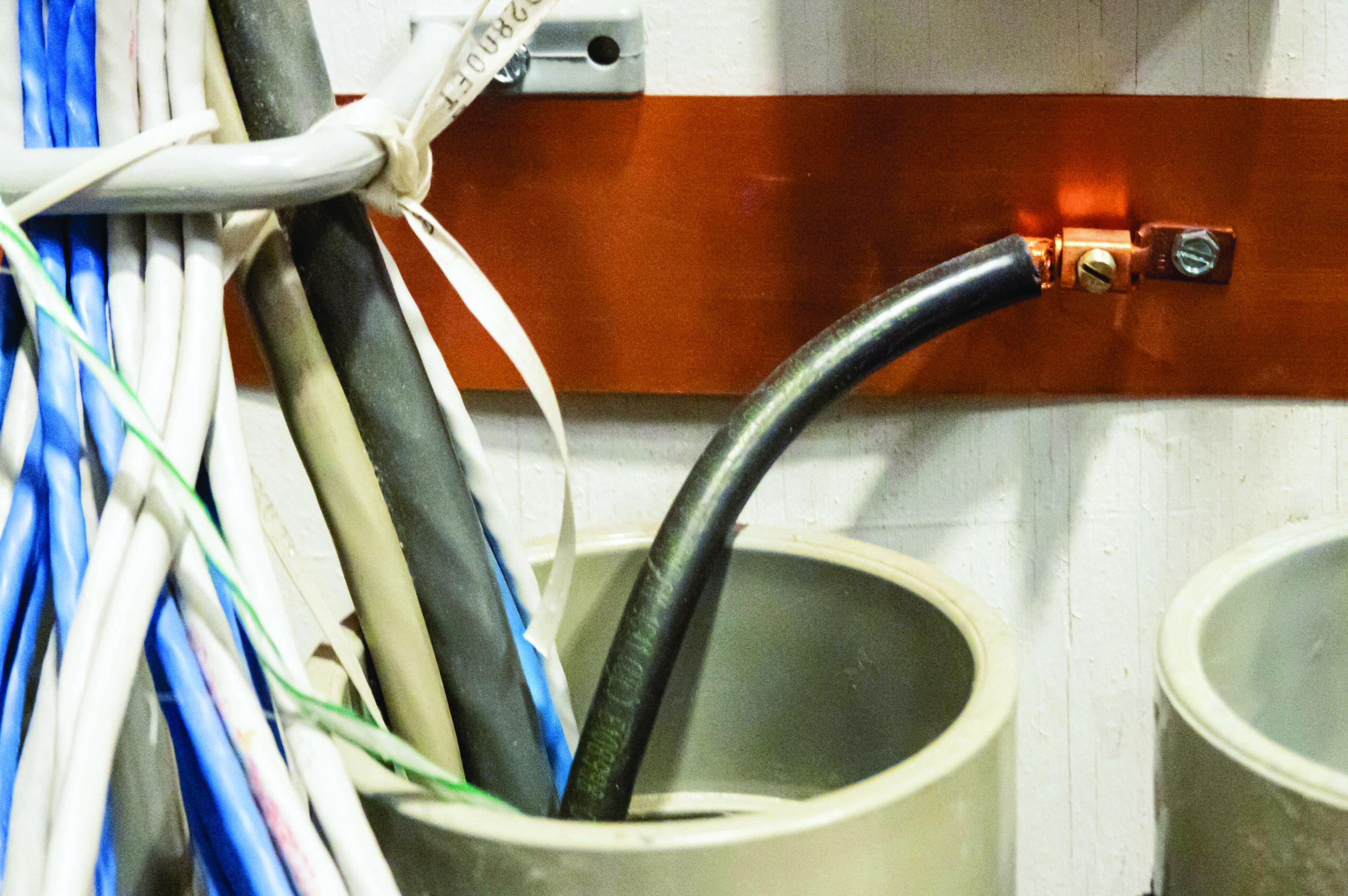
Heavy ground conductors should be run from the engineering/equipment room to each studio. Fig. 7 shows an RG-8 coaxial cable with the inside and outside conductors brought together at the end. It makes for an inexpensive low-resistance conductor that is insulated along the cable route because of its non-conductive jacket. You don’t want the ground wire to touch other grounds on the way. Accidental intermittent touching to electrical conduits, rebar in concrete, water pipes and whatever creates a difficult troubleshooting problem. Don’t let an unreliable connection happen as it could play havoc with audio and control for years to come.
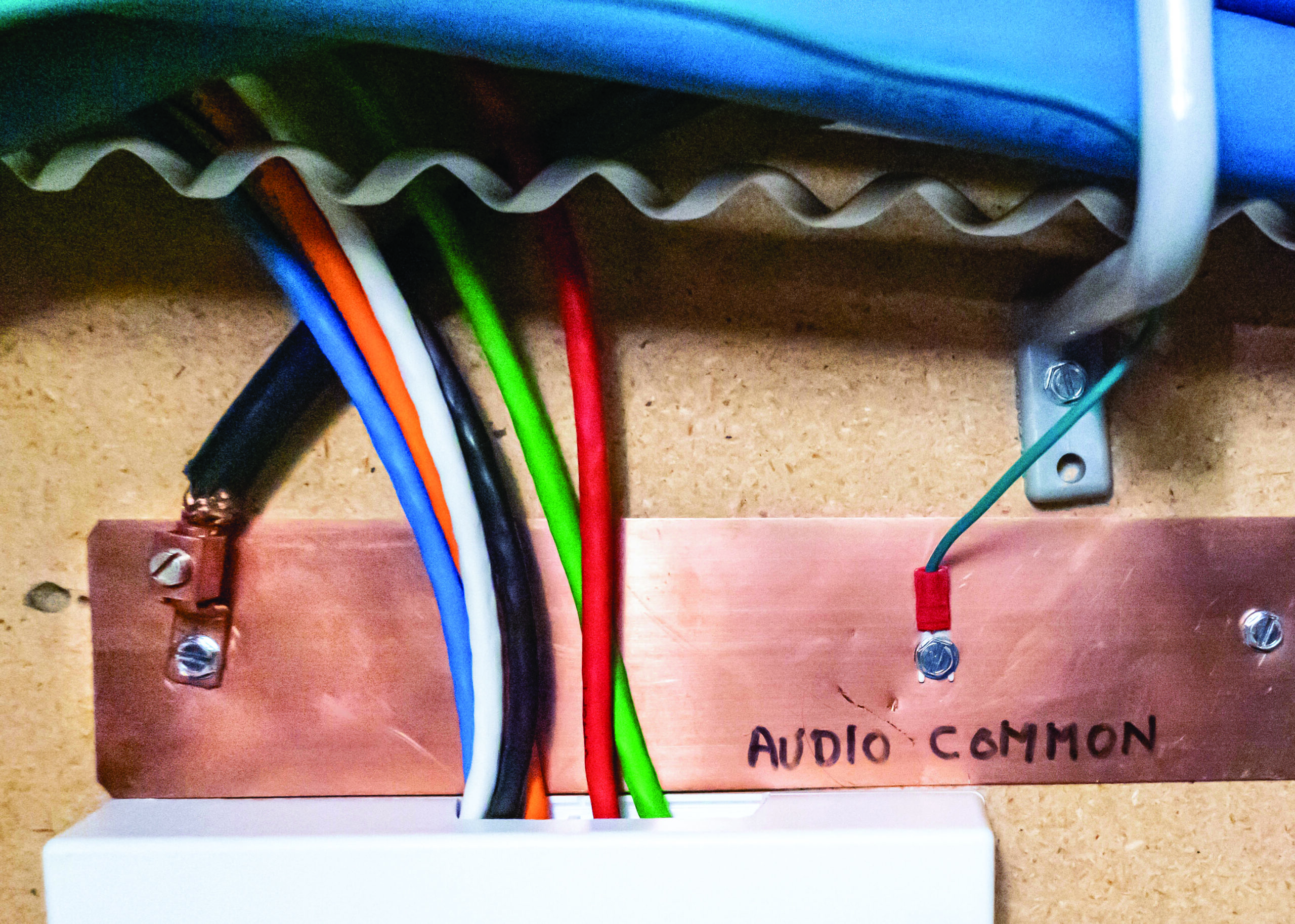
A single point ground is sometimes called a star ground, where the equipment room is the hub and studios are runs away from there. Every studio ground should be the other end of each RG-8 cable. Fig. 8 shows a 12-by-2-inch copper strap where studio devices connect. You could call this a mini-star hub leading to the equipment room.
Ground differences
Balanced audio can get into trouble if the ground on one audio device is more than a few volts different from the other. Audio could get noisy or distorted, or have hum. This should not be a problem when employing a star ground. I’ve seen it where the ground system is the last thought and must be put in later to solve problems. It sometimes confused or irritated people when I spent time carefully building a studio ground system before doing anything else. A good ground helps with lightning protection too.
In summary there are no concrete answers that fit every analog audio situation. Some experimenting is required. Knowing the pitfalls should help you get to the right answer. Think through and understand audio in the facilities you work on. Radio depends on keeping listeners who enjoy the sound.
Comment on this or any article. Write to [email protected].