Rob Atkinson, K5UJ, is an engineer out of Saint Charles, Ill., and one of the many readers who enjoy the DIY projects we feature from time to time in Workbench.
He writes in to say that he admires Frank Hertel’s ingenuity in home-brewing the LED dimmer circuit that we told you about in the May 26 issue. However, as a ham Rob is concerned about the RFI that variable square waves cause and that there was no mention of RFI mitigation measures in Frank’s submission.
Rob points out that any kind of control circuit based on square waves can be a terrible spectrum polluter, especially if the leads to the device being controlled are long and unshielded. His concern is that these ideas often end up on the internet, where they are repurposed by unsuspecting shortwave or medium-wave hobbyists.
Frank Hertel responded: “Since hams sometimes work with receiving weak signals” — which, by the way, Frank does when measuring distant AM and FM signals — “I can relate to Mr. Atkinson’s concerns.”
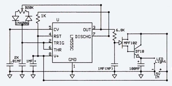
Frank says Rob is right. See Fig. 1, the dimmer schematic. The 555 Timer IC does produce a fairly square wave output, so filtering is important. However, the 6.8K resistor that is in a series with the 555’s output to the MPF102 MOSFET’s gate is bypassed to ground with a 1 MFD (nonpolarized) capacitor and does a pretty good job of turning the square wave into a semi-sine wave (non-symmetrical shaping).
Finally, an additional damping filter capacitor, the 100 MFD capacitor at the D718 emitter to ground that connects to the LED light fixture, does a bit more filtering.
Frank realizes that he could have fabricated a more sophisticated output filter network, but he found that any emissions from the dimmer circuit were consistent with the emissions of commercial dimmers and commercial dimmable LED lamps, so that is where he decided to leave it, as you see in the schematic.
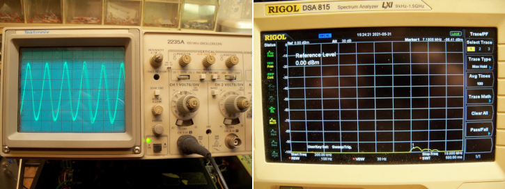
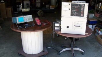
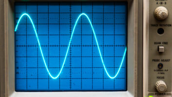
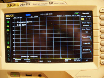
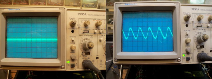
In these scope photos and spectrum analyzer shots, the probe is connected across the 555 output/LED fixture at different LED intensities.
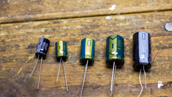
The Enemy of LEDs
San Francisco contract and project engineer Bill Ruck was interested in Frank’s dimmer circuit, but even more so in the super-flexible silicone wire used. At Amazon.com, type “B07K9R9LBV” in the search field to find this 22-awg silicone electrical wire. Frank used 22 gauge but other gauges are available.
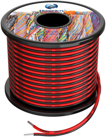
Bill inquired because most of the “zip” red/black cables that he has seen are relatively stiff. He points out that most LED fixtures have a built-in regulated current switching supply. If the fixture just had a current limiting resistor, it would dim gradually.
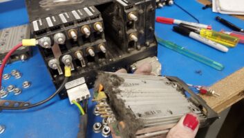
Bill related a personal experience in which he replaced his circular kitchen “dome” fixture with LEDs. It turns out the two round “Circline” fluorescent bulbs are no longer manufactured by GE, so Bill bought a “2600 Lumen 30W Super Bright Cool White LED” from MJPA (Item #31327 OP at mjpa.com) with the appropriate power supply. He then used the fixture can to build a LED-based lamp.
The lamp worked great for about six months, then failed. This time, he spaced the LED assembly below the ceiling with an extension box. This, too, failed in time. The repair saw Bill adding heat sinks around the LEDs.
The moral to the story? Heat is the enemy of long-life LEDs! Next time, Bill will rebuild the fixture and put the heat sinks on the outside of the can to better dissipate the heat.
John Bisset, CPBE, has 50 years in the broadcasting industry including 31 years writing Workbench. He handles western U.S. radio sales for the Telos Alliance and is a past recipient of the SBE’s Educator of the Year Award. Workbench submissions are encouraged and qualify for SBE recertification. Email [email protected].