Shielded-Loop AM Antenna
Oct 11, 2001 12:00 PM, BE Radio
AM Loop Anetenna for AM Reception
AM reception can be very difficult because of the inherent succeptibility AM has to electrical noise and other sources of interference. The built-in antenna in most receivers – a coil and a ferrite rod – is not sufficient for clear reception. An external antenna can usually greatly improve reception.
The loop antenna is a proven design. There are commercially produced models available, but, depending on the use, it is sometimes hard to justify the cost of the antenna.
What follows is a copy of a schematic I originally discovered around 1994, and I am told that it is from the Motorola C-Quam AM Stereo bulletin, issue 3, from 1989.
No guarantee as to the suitability or accuracy of this schematic is made or implied for its use or any undesired consequences resulting from its use.
Note: I have also made an antenna like this using three individual runs of a single-pair, twisted, shielded cable, such as Belden 9451 in place of the 8777.
Chriss Scherer
editor, BE Radio magazine
The original text follows.
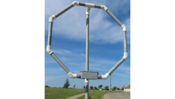
We’ve been asked to reprint this passive loop antenna design, offered by a C-QUAM station engineer in one of our previous bulletins. The loop self resonates approximately in the middle of the AM band, and by adding or subtracting turns it can be optimized higher or lower in the band.
Instructions for assembly:

- 1. Cut a seven-foot length of Belden 8777 or similar three-pair foil shielded audio cable.
- 2. Strip back two inches of outer jacket and foil from both ends. Cut the shield wire on the right-hand end of the cable, and tape or heat shrink the end to keep the cut-off ends from touching anything.
- 3. Wire the cable as shown above. We used six feet of RG-59/U to connect to the receiver.
- 4. Heat shrink or tape all connections.
- 5. The plane of the loop should be pointed toward your station. It isn’t necessary to support it as a geometrical figure, although a circle would represent the greatest area.


