The IBOC FM waveform
Feb 1, 2004 12:00 PM, By John Battison, P.E., technical editor, RF
The world of IBOC encompasses AM and FM operation. At the present time, AM and FM IBOC operation is in use by a number of stations. The use of AM IBOC at night is still under discussion due to a possible problem with skywave signals.
FM IBOC recently received a boost with the introduction of new antennas capable of dual transmitter operation and not requiring expensive and elaborate combiners. The FCC is expected to issue new FM IBOC antenna rules soon.
Table 1. The FCC-required channel occupancy.

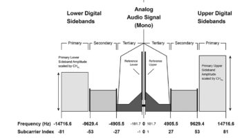
Figure 1. Hybrid operation with analog main channel.

Figure 2. Extended hybrid operation with analog.

The FM IBOC system offers four basic services in a single FM assignment. The main program provides audio, the personal data service offers miscellaneous data service as required by the user, the station identification service is provided by a third channel and the fourth auxiliary application service provides a broad choice of specialized transmission applications.
The IBOC system for FM as developed by Ibiquity is a fascinating engineering feat. A tremendous amount of engineering design was involved in complying with the FCC’s strict channel width requirements within which Ibiquity had to stay and still produce the desired results. The FCC’s rules require that all IBOC signals stay within the FM emission mask in accordance with the commission’s rules.
The sum of all parts
IBOC FM is a unique combination of many systems. In fact, multum in parva is the best way of describing its many parts. The complete operation is organized into five layers. Each layer performs a specified job, or jobs and the results in a data transmission system (including music and speech) that can be considered free from interference and possible errors within the limits of the transmitter’s service range.
The FM IBOC system has been developed as a series of layers, each of which performs a specific operation. From a standard broadcaster’s point of view, Layer Five is probably the most important. This is the speech input layer where audio is received, processed if necessary and passed on to Layer Four where it is encoded for digital transmission. The channel encoding counteracts the normal RF transmission imperfections, which can include fading, interference and atmospheric noise. Forward error correction (FEC) adds correction bits to the pretransmitted signal with bit redundancy being used to improve system resistance to errors.
Layers Two and Three perform the multiplexing, which is critical to the success of the IBOC system, and Layer One determines the format to be used for the actual transmission of the signal.
A logical channel is used to describe the optimum circuit path laid out for a signal to follow on its way through Layer One. Because the IBOC system accepts many different types of signal 10 logical channels are provided. Not all of these are used all the time depending on the transmission needs of the audio input. Four of these are classed as major logical channels, and the remaining six are used only with digital waveforms. A channel listing protocol has been established that provides a guide to the type of service required.
The waveform of the transmitted signal is different from anything heretofore observed in the FM band. IBOC offers different systems or protocols: hybrid, expanded hybrid and total digital. The three waveform characteristics, or spectra, are basically similar but have some clearly defined differences. However, each system’s spectrum is divided into a diverse number of sidebands, which represent different orthogonal frequency division multiplexing (OFDM) subcarrier groups.
All three of the FM IBOC transmission systems use OFDM for the digital portion of the signal. It uses the properties of OFDM, which is a parallel modulation system in which a number of narrowband subcarriers called partitions are simultaneously modulated. These narrowband sub carriers produce resistance to multipath, fading and interference because they are transmitted at a comparatively low symbol speed and provide a comparatively long information holding time.
One of the major differences between IBOC and other single carrier digital systems is the use of frequency partitions. Each partition consists of 18 data subcarriers and one reference subcarrier. The manner in which the subcarriers are handled depends on whether the IBOC system in use is the hybrid, extended hybrid or all digital.
The first two waveforms, hybrid and extended hybrid use an analog FM signal and differ in the sideband usage. As its name implies the all-digital system does not use any analog signal at all. The bandwidth of the sidebands from the main digital signal is expanded and lower power secondary sidebands are inserted in the space formerly used by the analog signal.
Hybrid operation
The analog audio channel can include stereo and SCA operation. Located on each side of the analog audio signal are the primary main sidebands. The sidebands consist of 10 partitions, which may be allocated among the various subcarriers. Two additional reference subcarriers are included in these sidebands.
Extended hybrid operation
To operate in the expanded hybrid condition OFDM subcarriers are added to the primary main sidebands in the normal hybrid configuration. As many as four frequency partitions can be added between the edge of each primary main sidebands and the analog signal. This is called the primary extended PX sideband. Figure 2 shows the spectrum in the extended condition and shows four additional subcarriers. The channel width is greater but still within the FCC’s requirements.
All-digital FM operation
Figure 3. All-digital spectrum with full channel occupancy.

The IBOC all digital mode produces a complex waveform. By disabling or removing the analog signal ample space is left to insert the primary digital sidebands and lower power secondary sidebands. Extended frequency partitions are present in this operation. Each secondary sideband also has 10 secondary main and four secondary extended frequency partitions and the secondary main frequency partitions are closer to the channel center.
In addition, each secondary sideband has a small, protected area located where there is least likelihood of interference from adjacent analog or digital signals. In this area are 12 OFMD subcarriers and one reference subcarrier. The center of the channel carries one more reference subcarrier. The resulting channel spectrum is symmetrical with several reference subcarriers available to ensure correct decoding in the receiver.
The frequencies span of the complete spectrum is 3.96803MHz, which falls completely within the commission’s general FM requirements. The total average power of a primary digital subcarrier is at least 10dB above the total power of the hybrid primary digital subcarrier.
Thanks to Jeff Detwiler of Ibiquity for providing information for this article.
E-mail Battison at[email protected].