Every radio or TV station engineer wants to have a reliable transmitter site. Specifically though, what is meant by reliable? Naturally we want any transmitter site to be trouble-free; we also want it to run consistently and be predictable.
On a personal note, no one wants to be called out in the middle of the night to fix transmitter site problems. With fewer and fewer staff responsible for more and more remote sites, we seek to minimize unscheduled, emergency trips. We want reliability, consistency and predictability at any transmitter site; the achievement of those qualities is what this article is about.
Much of this material has been covered in the pages of Radio before, but these points can never be emphasized enough.
SHELTER
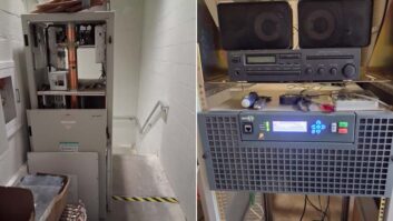
As an engineer dealing with remote sites, it isn’t just the equipment that you need worry about; all manner of things can happen to an unattended site sitting out in the middle of nowhere. Having a poor shelter, for example, can lead to many other problems.
Creatures of the wild are often attracted to the shelter and warmth of transmitter buildings. Aside from having to clean up big messes left from mice that sometimes build nests in equipment, a more serious problem can come from the fact that rodents have a tendency to eat wire insulation. This can lead to open circuits, short circuits or other issues that show up if water happens to touch the wires for some reason.
Rats and mice will often die right in the transmitter building, leading to further messes and awful smells. Snakes are another matter. I haven’t had much experience with them; however, I did once clean a tube-type transmitter that had been invaded by a snake. It had come in through a transmission line conduit and decided that the HV power supply was the place to be, with predictable results. That was nearly 30 years ago, and I can still remember how bad it was.
Water is another common issue at a transmitter site. An obvious problem is leaks through the ceiling that drip right in to the top of your transmitter or rack. A less obvious issue is condensate from an air conditioner with plugged drains that manages to drip into a transmitter or rack. The worst scenario with water is flooding, of course.
A large part of site management is mitigating the problems I’ve mentioned so far. If you are sharing space with other tenants, especially those with outside walls, you’ll be challenged to keep varmints out because many of the ingress points are outside of your control. All you can really do is exercise your rights in the lease and have the landlord keep these problems in check. On the other hand, if the site belongs to you, I recommend the following:
Carefully block all potential ingress points for mice, rats and snakes. This includes windows, holes that pass coaxial cable or conduits outside, vent holes and door seals.
Look for water leaks while it is raining. Sometimes you can find evidence of leaks after the rain has passed and things have dried out, but it is much easier to see where drips are originating while they are actually happening.
When air conditioners are installed, plan for appropriate drainage. Having drip pans underneath air conditioners is fine, but if the drains get blocked the condensate water can end up in places that you don’t want. Avoid placing pans or drain lines over transmitters and racks if at all possible.
Flooding. The prevention of flooding is something you can really only do when the site is being constructed from the ground up. For AM sites, if a site is built in a flood plain, plan for a height that will accommodate at least a 100-year flood level. Include the building, ATUs and tower bases. As for mountaintop FM sites, consider the possibilities of landslides that could damage your building from below (washouts) or from above (mudslides).
A major part of building a reliable transmitter site is anticipation of things that could go wrong. The four items I’ve just mentioned are predictable and can be addressed ahead of time.
ALTERNATE POWER SOURCES
It’s only after you’ve generated your own power for more than several hours that you begin to realize how difficult it can be. Your local utility does it 24/7/365 so of course, they have it figured out (for the most part).
If you are installing a new generator, your design issues are size and runtime. If the transmitter site already exists and all loads are wired to the same distribution panel, then clearly the generator will need to be large enough to power all the loads. If you are starting from the ground up, you might want to consider having an emergency panel, which is one that is sourced from the automatic transfer switch, but does not power all the loads.
Fuel storage is always a difficult problem because one must balance the maximum anticipated runtime against the cost of the fuel, the cost of storage vessels and even fuel maintenance. Always remember that the situation causing the power outage is also likely to cause problems for your local utility and the fuel company you use. If you normally maintain enough fuel to run 36 hours (for example) and find later that the road to your transmitter site is closed and cannot be reopened for several days, then trouble is at hand.
I’ll offer up one piece of advice here: Get it all going in. You’ll find it far easier to get money to install a larger generator and/or more fuel storage when the project is in the design phase than you will if you try to get everything upgraded after the fact.
Clearly, regular generator maintenance is crucial to your peace of mind, and nothing solidifies it more than testing the generator under load. During this test, all the various elements of the system get used in an “emergency” situation. Predictability is what is important here. You need to know what is going to happen when there is a power failure at the site.
During the test, look for the following:
- After the transfer occurs, your normal air-chain should power up and all user-selected configurations should be remembered. It should require no intervention.
- All UPSs should have no problem running on generator power.
- Any remote control signaling regarding the generator should be active. Likely you’ll have “generator running” status along with “generator transferred to load” status.
- All IP network equipment restored and automatically connected. E-mails regarding transfer should have gone out and been received by the far end devices.
- Upon re-transfer, all elements of the air chain should continue without problems, obviously. The generator should have a cool-down period after the re-transfer of 10 to 15 minutes.
- Remote controls should indicate the generator is off-line.
- There will always be some question as to length of the load-test. From my own experience, I would recommend at least 4 hours. Just remember: The longer it goes, the more confidence instilled. If you schedule regular infrared testing of your electrical system, it’s a good idea to do so while testing the generator under load, because it allows you to test the integrity of the electrical connections that are not normally used.
There are two schools of thought regarding the testing of generators without the load. Many (including myself) have tested generators on a regular basis without a load attached. Still, many other users insist that it’s ultimately harmful to the generator to do so. It’s beyond the scope of this article to get in to the reasons for that. I suggest you consult your manufacturer’s rep or your maintenance company to help in deciding what to do.
One cannot forget about the generator between test periods, though; far too many things can happen to it. Monitor the following on your generator during its quiet periods:
Remote diagnostics via serial or network connection. Run the user interface on a computer that is remotely accessible, and look in on it periodically.
Operation of the block heater. A failure of the block heater doesn’t equate to a failure of the generator, but keeping an eye on the unit is a good idea. You can do this easily enough by measuring the current draw of the block heater itself. Monitoring will likely require a remote control that can be scripted because you won’t want constant status changes caused by the heater going on and off, but you will want to know if the operation is normal over a test period of 24 hours.
Battery voltage.Without a properly charged battery, the generator isn’t going to start, no matter what. Monitor the battery “float” voltage with alarms that let you know if it is too low or too high. “Too low” likely means the battery isn’t properly charged, while “too high
likely means that your battery charger is boiling off the electrolyte, leading to eventual failure.
ENVIRONMENTAL CONTROL
The near-ubiquity of microprocessors at transmitter sites makes environmental control much more important than it once was. In the “old days” you could get away with much wider temperature swings inside of a transmitter space than you can expect to now.
Like generators, air conditioners are used to solve one set of problems at a remote site, while bringing their own new set of problems along for the ride. As with generators, it’s likely that you’ll hire a service company for their maintenance. It’s a good idea to test your service company’s “after-hours” response on occasion, to make sure you have the correct phone numbers (they do get changed sometimes, after all) and just to see how long response time is.
If you are building a new site or replacing older A/C units, it’s a great idea to look at units that have remote access. One such line is the Challenger series from Liebert.
With IP access to A/C units, you’re presented with several advantages:
- Access to the operation of the unit, often on a very granular level ofdetail
- Email alerts in the event of problems
- If the unit supports SNMP, then you can monitor it automatically and continually without having to resort to Web access.
Obviously not all units have this capability and you may be saddled with an inherited, “old-fashioned” unit. There are still measurements that can be made that will allow you to see what is going on from afar. For example:
- Measure room temperature at a spot in the room where the air is “mixed” — in other words, not too close to the cold air outlet of your A/C unit, and not directly above a transmitter exhaust.
- Separately measure the outlet air temperature of your A/C unit.
- In the event you receive a “high temp” alarm in the transmitter space you can then check the temperature of the A/C unit’s output air, to see whether or not it’s cold. If not, clearly you have a problem.
If you want to take a more proactive approach, consider the following steps:
- Measure the room temperature and the A/C output temperature separately.
- Detect if the A/C unit has been called upon to provide cooling. This will require a remote control that supports scripting. Compare the “calling” of the A/C unit with the cold air output temperature of the A/C unit. If the thermostat is calling for cold air but none is coming out, you have a problem on your hands.

The advantage to this method is that you’ll be made aware that a problem exists before the room temperature gets out of hand. This is also why you’ll want to know your service company’s after-hours number. This kind of problem never seems to happen during business hours.
REDUNDANCY IN AIR CHAINS
System redundancy is the key factor in the creation of a reliable transmitter site. There should be no “single thread” systems, every element of which is a single point of failure. Each element of the transmitter facility should have a backup.
There should be at least two means of getting program from its origination point to the transmitter site.
- There should be at least two transmitters.
- Having access to two antennas is very desirable.
Ideally you will be able to deliver program audio to the transmitter site via a “wire line” of some type as well as a radio circuit. The reason for this is simple: The types of failures experienced by one type don’t have anything to do with the types of failures experienced by the other.
Radio links can be disrupted by failure of the equipment, transmission lines, antennas or interference. “Wireline” circuits can be disrupted by physical failures such as cut cables or fiber, or a power failure at the central office or somewhere else along the path.
The key is to build your system such that an unfortunate event that disrupts one studio-to-transmitter (STL) link doesn’t disrupt the other at the same time.
There are far more options for both radio and wireline STLs than there were just 10 years ago. In addition to 950 MHz band radio systems, we now can complete the “last mile” connection via Part 101 radio systems (such as licensed 11 GHz radios) and of course, you can always try an unlicensed ISM band radio system. In terms of “wirelines” we now have DSL and metro Ethernet in addition to the legacy TDM types such as T1 and T3.
Aside from two program outputs from two separate STLs, it’s a good idea to have two separate audio processors as well. The reasons for this are simple: Most (if not all) of the features that we expect of audio processors nowadays can only be accomplished by means of embedded software.Even the most well-designed hardware can be brought to its knees if just the right quirky “glitch” conditions occur.
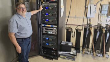
Once you have the gear in place, you’ll have to determine the best way to connect all of it together, being careful not to develop any SPOFs. Where I work in Los Angeles we’ve developed what we refer to as the “matrix.”A Burk U.I. (by Dennis Sloatman) is shown below in Figure 2.

From left to right: We have a four-input audio switch (using magnetic-latching relays) that chooses one of four program audio feeds that are sent to the input of one of two audio processors. At the far right we see both main and auxiliary transmitters. Each has a two-input audio switch (again, magnetic-latching relays) that can be fed from the output of either audio processor. In this fashion, we can use any audio source, by way of either audio processor, for either of the transmitters.
Having more than one transmitter is probably considered a luxury by some, but it’s inevitable that a single transmitter will need to be “off” at some point, whether it is because of a failure, a tube change or a software update. Even the most modern solid-state transmitters need a break now and then. When that occurs, your station is essentially “out of business.” As part of the creation of a reliable and predictable transmitter site, having at least one auxiliary transmitter is a must. It may be difficult from a budget standpoint to justify such an acquisition, but there are some options:
- When obtaining a new transmitter, keep the “old” one, and use it as your backup;
- Buy a second transmitter on the used market, restore it and use it as your backup;
- Buy a low-power transmitter for use only as a backup.
With two transmitters in place, you’ll need a way to switch their outputs between the antenna, and a test load; so when considering the budget for such a project, don’t forget these two vital items. If you want to have access to the RF coaxial switch by remote control, you may want to consider a commercially available RF switch and transmitter controller. Take a look at Figure 3.
Tunwall Radio makes a nice line of antenna switch/transmitter controllers that are based on programmable logic controllers. I should also mention, though, that if you have a remote control that will do scripting, you can roll your own “controller” fairly easily by interfacing it with your coaxial switch.
You may have noticed from Figure 3 the controller is designed to accommodate three transmitters and two antennas (for an FM system). Those organizations that consider a second transmitter to be a luxury would obviously feel the same way about a second antenna, but there are plenty of reasons for having one.
In FM systems, for example:
- Failure of one or more antenna elements
- Failure of the transmission line
- Necessity of lowering power for the accommodation of tower climbers

For AM directional antennas, it makes sense to consider backup in case of failure of transmission line, the phasor or another antenna system component.
An antenna or transmission line isn’t something that you can necessarily just repair in an hour or two. The way to minimize repair and off-air time is to plan for it before it ever happens. For an FM station, this would mean installing another antenna and transmission line on the tower (or preferably, an adjacent tower). For an AM directional, this would mean having an easy-to-use “non-D” tower that you could switch to (albeit at lower power) while you analyzing the problem with the directional system.
SINGLE POINTS OF FAILURE
I alluded to SPOFs earlier — but what exactly do I mean by that? When you build multiple, parallel air chains (as described earlier) there will always be the temptation to use elements that are common to both chains.
Here are the most common examples:
- Multiple air chains all energized by the same circuit breaker
- Multiple air chains all energized by a common UPS
- Multiple air chains that share a distribution amplifier
- Multiple air chains that share an active switch (i.e. one that needs power to pass signals)
There are subtle SPOFs though, some of which may be impractical to circumvent:
- All AC power comes from one panel that is fed from an automatic transfer switch (ATS)
- Two telco wireline sources that originate from the same telco rack that has no emergency power
- Two radio STL receivers fed by the same dish and transmission line
- A single transmitting antenna (AM or FM)
Consider the common SPOFs first. You must never allow the failure of a circuit breaker to de-energize both air chains. If you have more than one rack, make sure that each rack is fed from a separate breaker in the distribution panel. Put one air chain in one rack, and other air chain in the other rack. If you have no choice but to put everything in one rack, see to it that there are two AC power sources in the rack. Use one circuit for one air chain and the other circuit for the other. Label the individual elements of the air chain as to their specified AC source. (See Figure 4.)
UPS failures are all too frequent because when they are installed, it’s easy just to plug every element of the air chain into it and then walk away. UPSs at the transmitter site have become common as equipment has become more sophisticated and sensitive to power interruptions. Just as with the AC power sources described earlier, don’t plug each element of each air chain into the same UPS. Either place one UPS in each rack, using different ones for different air chains, or if you are stuck with a single rack, have one outlet strip energized by the UPS and one energized by “raw” AC power. Plug one air chain into the UPS and one into raw power. That way if the UPS fails, you’ll still have an air chain to work with. As you recall from our matrix discussion earlier, that one air chain should be available to at least one of your transmitters. Finally, don’t plug the UPS into that same raw source. Use a different breaker for it.

Never allow a distribution amp (DA) to take you off the air. What I typically do is to “bridge” the DA input across program feeds that need distribution. The actual on-air feed does not go through a DA itself. I’ve seen instances in which both air chains actually went through a common DA. In this case, a single popped fuse could take the radio station off-air.
Since AES I/O in STLs is common nowadays, it’s tempting to use an AES DA to drive multiple air chains. You have the same potential problem here as with the older DA types; one blown fuse takes the radio station off the air. We do two things to get around this: AES distribution is done passively with AES splitting transformers and AES switching is done with devices that are based on magnetic latching relays. These have the advantage that they are totally passive — needing no power to pass signals — and naturally they work fine passing audio as well. The disadvantage is that when they switch, any AES receiver immediately downstream needs to re-sync, leaving a short gap in your audio.
The more subtle SPOFs can naturally be harder to “see” at first. Rare is the transmitter site that has more than a single ATS, but this is another common spot for major failures. The way around this would be to have two ATSs, one feeding one air chain and transmitter, and the other feeding another air chain and transmitter. (See Figure 5.) Granted, this is probably not a practical solution for most stations. The best you can do is to carefully maintain the ATS and all associated wiring and contactors. Perform regular IR testing on the inside of the panel(s) with the load energized. This is standard operating procedure in many office buildings.

Local exchange carriers that maintain large mux/de-mux facilities at transmitter sites often don’t pay close attention to backup power. You may see arrays of batteries all connected to provide 48 VDC, but do you have any idea how long those will last during a power outage? My point here is that you may have a “main” and “backup” program circuit (or T1) from telco, but if they both come out of the same de-mux rack, they’ll both die at the same time if the power is out too long. The solution here is to not rely on wire line for both the main and backup STL.
Likewise, having two radio STLs is great, unless a common antenna and transmission line feeds them. Two STL receivers ideally will be fed by two separate STL receive antennas; that way, when one dish gets blown out of alignment in a storm, or gets struck by hunks of ice falling off the tower, you don’t lose the signal for both STL receivers.
REMOTE ACCESS
For many years most of us were satisfied with simple telephone access to the transmitter site. With the proliferation of devices at remote sites that support IP communication, however, telephone access isn’t really much good anymore (except perhaps as a backup). IP support from remote devices also typically affords us much more granular detail about what is going on in a device or system.
You can make use of IP connectivity in one or more ways:
- Browsing into the site (HTTP)
- Having devices e-mail you with issues (SMTP)
- Having devices send SNMP traps
- Constantly measuring certain parameters via SNMP
Once you start taking advantage of the new features offered by devices and remote controls, the importance of constant and reliable IP connectivity increases. In most cases you would use private network connections at your remote site since one end of the connection is probably at your studio location. Having alternate IP access is ideal, but not practical in many cases.
You may have two STLs that can carry IP traffic or you may be able to obtain a DSL (or even a T1) from your local telco to provide a second means of communications. In that case you would use a router to allow incoming packets to reach the LAN via one or the other path. A more practical approach might be a second remote control that would have its IP connectivity served by a second network. This second remote control not only allows backup IP communications, but backs up your primary remote control as well. Virtually all current remote control manufacturers provide IP support, including Burk, WorldCast Systems, Broadcast Tools, Davicom, Statmon and Sealevel.
The reason we all want reliability at remote sites is because none of us want interruptions to our daily lives and routines. Due to the 24/7 nature of our business, failures at remote sites often require one to drop everything and go to the site to take care of whatever issue exists. However, with proper planning and implementation of the techniques described in this article, the number of emergency calls can substantially reduced — not to zero, of course, but close to it.
Perhaps most importantly, with reliability, predictability and consistency at your remote sites, you will likely be able to deal with these emergencies on your own terms, instead of the other way around.