At about this time last year, the all-digital future of AM radio was pondered in this column. In that article, I stated that moving toward all-digital and dumping the hybrid mode was the way to go.

The intervening year and 2015 NAB Engineering Conference have only served to galvanize that opinion even more.
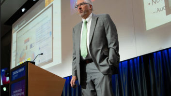
This year, David Layer provided additional information on the ongoing field-testing that NAB Labs has been undertaking for several years. The field-testing has wrapped up; however, additional projects continue. The field testing results have been spectacular thus far, and really serve to illustrate why this is a viable concept, despite the shrinking chorus of naysayers from the peanut gallery.
It is important to remember that all-digital is currently only authorized for experimental purposes by the commission. Therefore, anyone not connected with the field tests, in the reception area of one of the nine stations utilized for testing or in attendance at one of the recent presentations has likely based their opinion on experience with the hybrid or MA1 mode. The current MA1 mode was always intended to be a stepping-stone to the full digital MA3 mode and does not reflect the true benefits of the scheme.
MA1 MODE
In a nutshell, the field-testing essentially demonstrated that the all-digital mode works under all circumstances where the analog mode functions. Additionally, coverage under all-digital is very similar to that under analog. In many cases, the field-testing demonstrated that the all-digital coverage exceeded the analog mode.
One very interesting observation made during the testing performed in the Twin Cities metro area was that the all-digital mode experienced no dropouts on the test runs, while the hybrid mode experienced a substantial number.
Given that in the MA1 mode the digital carriers exist from roughly 10 to 15 kHz out from the carrier frequency, this may not be all that surprising. For in that region, there are adjacent stations operating, and their interference can certainly plague the operation of the digital sidebands. When in the MA3 mode, the carriers are located within 10 kHz of carrier, and if the secondary and tertiary are dropped, are within 5 kHz of the carrier. It should be self-evident that in confining the information to that chunk of real estate would reduce such events.
It has often been said that an AM antenna is a living, breathing animal, and as in the case of its biological analog, no two are identical. With this in mind, the question could be posed as to whether or not NAB utilized a broad enough sample to definitively say that the all-digital will work universally. After all, as of March 31, the commission counts 4,702 total AM stations licensed by them.
While that is a fairly large range of possibilities to consider, NAB Labs really did a good job in their sample selection. Stations of all classes were considered. Additionally, non-directional and directional antennas were considered. The sample also included stations located up and down the dial. Although it would have been very interesting to see what happened with tests on one of the big gun class A stations like WLS, WGN or WBBM, testing on WBT in Charlotte was certainly illustrative.
MA3
A question in the back of my mind after the 2014 presentation was how well MA3 would work for skywave coverage situations. The testing performed at WBT demonstrated that it would indeed function very well.
But, since skywave signals are inherently variable, some differences in quality were noted. In the 2015 presentation, audio clips were presented comparing both the analog and MA3 modes from WBT as received in the Boston region, and the difference was impressive.
For the testing, the team utilized OEM Ford vehicles, each with a digital-capable radio. No special changes were required to be made to the radios; any current receiver that works with the analog and MA1 modes will also work with the MA3 mode. Since no custom interface was present, audio was taken at a speaker input and fed directly into the computer. Therefore, when audio was present, successful reception of the digital signal occurred. As pointed out in the related paper, one drawback to this technique was determining if silence was due to program breaks or an actual loss of signal. To work around this, a barely audible 25 Hz tone was injected into the audio chain at the station. The recording devices would then look for this tone, and if present, consider that valid reception was occurring.
The operating power for each station was determined through the direct method. In each case, the base current or common point current, depending on the type of station, was adjusted in the MA3 mode to equal the licensed value in the analog mode. The locations of field strength contours were then determined to identify areas where the signal would potentially drop. During the drive tests, actual field strength measurements would then be obtained at the locations where the reception was no longer viable.
These field strength measurements were made with the FIM-41 and PI-4100 models from Potomac Instruments. These meters, however, are designed with a bandwidth that is much narrower than the digital signal being considered. As a result, a correction factor of 3.9 dB was suggested by the manufacturer for measurements obtained with the PI-4100. The necessary application of a correction factor brings up a potentially interesting problem for the future. Ultimately, a field strength meter that does not require the application of correction factors will be necessary.
In addition to the real world, testing that has taken place, and is more or less concluded, there is a laboratory-testing phase that continues. The controlled environment that a laboratory provides is essential in the study of potential changes to allocation standards that may be required. Since the all-digital mode has a greatly reduced bandwidth over the hybrid mode, adjacent channel interference will necessarily be less. Extensive testing of the hybrid mode was performed before its use was even authorized by the commission. As a result, NAB Labs points out, it probably is not necessary to perform additional such testing on the MA3 mode.
TESTING CONTINUES
Additional testing of co-channel interference situations would seem to be warranted. This is due to the fact that the digital sidebands adjacent to the carrier frequency are higher in power. Since the potential time frame of all-digital was below the horizon when the MA1 tests were performed, no co-channel evaluation was considered early on. Also, as Layer points out in his paper, the power spectral density of the MA3 signal is much higher than an analog signal, thus co-channel interference will be greater from an all-digital signal than from its analog counterpart. NAB Labs had not, as of the time of the convention, completed the co-channel interference testing.
Finally, any conversion process involves a fair amount of planning and execution to ensure a smooth transition.
One of the elephants in the room has always been the antenna system. For a single stick non-directional, the conversion should be fairly straightforward. However, with a multiple tower directional array, the costs in labor, resources and sanity can spiral upwards at a robust pace.
If your system is already functional in the MA1 mode, then minimal changes would probably need to be made for MA3 operation. This is due to the fact that the MA3 spectrum occupies less bandwidth than the MA1 mode, and as such is apparently not as taxing on designs.
Current numbers of receivers is above 25 million. That is definitely better than a couple of years ago, but is still well short of the estimated 1 billion analog receivers. All major auto manufacturers now have at least one model available with an HD radio, and many have entry-level vehicles with such technology. Granted, there will be some more time involved before we hit a critical mass on receiver penetration, but that day will arrive.
Translators have been a huge success for AM broadcasters, but they are a bandage over the problem. All-digital AM looks to be the cure for the ailment.
Ruck is principal engineer with Jeremy Ruck and Associates. He is based in Canton, Ill.


