Great ideas in studio design
Dec 1, 2008 12:00 PM, By Doug Irwin, CPBE AMD

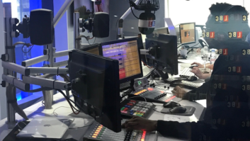
WNYC in New York City’s large newsroom. Photo courtesy of The Systems Group.
During the planning phase for construction of a radio station experience will come in to play, along with desires to do something new. Sometimes when confronting design problems it is helpful to have access to other engineers’ approaches to the same or similar problems. This could go on for page after page, but I’ve picked some good recent examples: an easy way to get access to dozens (or hundreds) of audio sources from your networked PC; a means to mitigate lightning damage in the worst of circumstances; a way to handle the selection and distribution of mix-minus feeds for multiple radio stations all under the same roof; and finally a convenient way to solve the age-old problem of off-air reception at the new place. Take a look. I think you’ll find all of them to be interesting.
Multiple monitors
In the �old� days, one feature of a radio station technical facility was a means by which audio from multiple sources could be sampled at multiple locations. There are many examples of how this was done: The most modern and effective means up to this point was having a routing switcher, and having a router head at each of the locations.
This is somewhat of an expensive proposition. Some routers could alternatively be accessed via a virtual control panel that would be live on a computer workstation, but even this required the use of a router output; so the proposition was still quite expensive.
Before that, likely the station had an array of pushbutton panels; a good example of that would have been the PR&E LS-10. However, if you were building a newsroom for a well-staffed news radio station, you could have a dozen or more switch arrays such as this. Installation of such a system would have been time-consuming, and therefore very expensive. Dedicated pairs of wires needed to be installed and were used (however frequently or infrequently) for this purpose alone.
Going back even farther than that, you would often see homebrewed switch panels, all made by someone in the engineering department, installed at each location. My favorite version of this was the rotary switch/Op-amp Labs/4-inch speaker built into a bathtub chassis. Of course it worked great until the rotary switch got noisy. Then someone had a big soldering job ahead.
So fast-forward back to the present. If you were building a new studio facility, what would be the best way to handle this requirement? Could there be a streaming audio approach? One that would make use of the computers you already have at each workstation, along with the network wiring already installed? A method that would effectively add nothing to the wiring costs? Of course there is: the Audio TX Multiplex.

Audio TX Multiplex
Multiplex is a system that consists of the audio server with associated software, along with client software (called Audio TX Multiplex Receiver) for each of the workstations in use by those who need access to multiple audio sources. One server can give access to as many as 96 audio sources for the system; an additional server(s) can be added to handle more audio sources. The server accomplishes IP multicast so that multiple users (over a LAN or WAN) can access the streams simultaneously. The system is licensed based on the number of audio sources that make up the system. Each of the source channels can be configured for different levels of quality; for example, 20Hz to 20kHz audio bandwidth, uncompressed, with a 48kHz sample rate would represent the high end of the quality scale. The user can also select lower sample rates, mono as opposed to stereo, and data compression schemes such as MP3 and MP2 with mono data rates down to 64kb/s.
Great ideas in studio design
Dec 1, 2008 12:00 PM, By Doug Irwin, CPBE AMD
One very slick and impressive installation of Multiplex in the field is at WNYC in New York City. WNYC has just completed a very large facility build in the SOHO neighborhood. As the NPR affiliate in New York, the newsroom is very important, and very large; that department’s staff is made of 30 people. (Jim Stagnitto, WNYC director of engineering, was kind enough to show me the installation.) The WNYC system has 32 inputs, which include studio program feeds, network feeds and of course local sources such as other radio stations in the market. The client software is opened on any one of the workstations on the network, and after the source is selected via the very simple GUI, the audio plays through that workstation’s speakers. Great functionality is provided to the newsroom personnel. Engineering and production personnel can also use it for quick troubleshooting while sitting at their desks.
Better connections
One of the ironies of new studio construction projects (and often existing locations as well) is that there are off-air reception difficulties. It could be difficult to pick up one of the stations housed in the facility itself; it could be difficult to pick up an important competitor; it could be difficult to pick up a news source; or it could be tough picking up your designated EAS source or sources.

Clear Channel NYC recently consolidated five stations.
Many years ago I was the chief engineer of Wild 107 (now Wild 94.9) in San Francisco. We competed against two other stations for what was essentially the same audience group across the entire Bay Area. The PD wanted me to make an air monitor signal available to the jocks not only from our San Francisco competitor (KMEL) but also from our San Jose competitor (since this was an embedded market) known then as Hot 97. The challenge lay in that it was impossible to pick up Hot 97 in San Francisco; not only was it about 40 miles away, but it was separated from us by the hills that make up the San Francisco peninsula. Add to that the fact that our studio was near Fisherman’s Wharf in the city, adjacent to Telegraph Hill. We had a hard enough time picking up San Francisco stations there, let alone a San Jose facility.
But I wasn’t one to simply say it can’t be done before giving it some thought. As it turned out, this PD lived on the Peninsula, about 20 miles or so south of our studio location, and at his house, Hot 97 came in fine. So if you’re guessing now that I put a receiver in his garage, and dropped an 8kHz phone line in, you’d be correct. Problem solved.
So fast forward 15 years to New York City. Clear Channel recently completed a large consolidation project, putting all five of its NYC FMs (WHTZ, WKTU, WAXQ, WWPR, and WLTW) under one roof in downtown Manhattan. One of a myriad of engineering problems that needed to be solved was making six EAS sources readily available in our master control, so they could be distributed to the various EAS codecs located across the facility. Our five stations required the six sources not only because of the guidelines of the NYC EAS plan, but also because WHTZ Z100 is licensed to Newark, NJ, and follows the New Jersey state plan. Its designated sources (WFME and NJN, the New Jersey Network) come from New Jersey.
Even though our location is way downtown in Manhattan, and our building kind of lords over the neighborhood, it’s still, for the most part, impossible to pick up the two AM sources we needed (WINS and WABC) in our 3rd floor MCR because our building is of an old-fashioned design (lots of steel) and AMs don’t penetrate well. The FM and NWS sources come in better, but reception of them on the 3rd floor is subject to multipath that frequently changes. We planned on accessing NJN via off-air reception of channel 51 TV transmitted from Montclair, NJ (northwest of Manhattan), so multi-path issues were feared for it as well.
Great ideas in studio design
Dec 1, 2008 12:00 PM, By Doug Irwin, CPBE AMD
If you have worked on a large radio station facility construction project you know many of the problems are solved empirically after the fact either because they are unknown during the planning phase or because some parameters or circumstances change between the time the planning is done and the time that the facility is finished. We found that reception of our EAS sources was more problematic than imagined during the planning phase of the project. Perhaps this is my favorite type of challenge during a large project such as this: studying the problem at hand; looking at the resources that are available; and then crafting a solution. I remembered the solution I had come up with 15 years earlier to pick up Hot 97, and I decided it would be a lot easier to receive the sources where they were strong and clean, as opposed to fighting weaknesses in Manhattan. However, 8kHz phone lines for transport were not in the cards.
The Empire State Building is still the tallest structure in Manhattan, and as you can imagine, picking up VHF signals on the 83rd floor there is quite easy. WQXR and NWS were two sources we needed. WQXR transmits from Empire, so it was a slam-dunk. One of our local NWS transmitters came in fine there, too.
The top of our building in Manhattan is at about 500′, not really surrounded by other buildings, and a couple of our other sources, namely WFME and WINS, were easy to receive there.
Our disaster recovery site, located in New Jersey west of Manhattan, was a great location from which to pick up WABC, along with NJN on channel 51.

Barix Instreamer 100 (top) and Extreamer 100.

One of the modern aspects of our new build in Manhattan was high-bandwidth, highly accessible network access at all the sites (including the roof of our building). For this reason I decided to use high-quality streaming audio to bring all the various EAS sources to our master control. The equipment I chose for the job was the Barix Instreamer (encoder) and Exstreamer (decoder), although there are other streaming appliances available as well.
The Instreamer is a small network appliance (3″ � 4″ � 1.5″) that has two IHF audio inputs, an RS-232 port (DB9) and an Ethernet port (RJ-45). The unit must be configured by the user; but it’s easy to do. Connect to it via serial, or use a crossover cable directly to a computer. Open a browser to access the configuration menus. Tell the Instreamer its network address, subnet mask and gateway. Then set the quality level of the MP3 stream to be generated; and finally tell it the address of the target decoder. Plug in the network connection.
On the opposite end, the setup is similar. Connect to the Exstreamer, provide its network address, subnet and gateway. Connect the network. Pull audio out of the IHF connectors. Within a short time you will hear the audio coming from the far end. Reconnection is automatic, in the event the connection between the two units is lost for whatever reason.
Great ideas in studio design
Dec 1, 2008 12:00 PM, By Doug Irwin, CPBE AMD
Since the Instreamer/Exstreamer pair will each handle two channels of audio, we have one at each of the three sites I mentioned above. Gone are issues with multi-path, fading, and impulse noise. Our EAS sources are consistently available and clean thanks to this modern solution to an old problem.
Arrested lightning
Being an east coast transplant I can’t say I’ve had that much experience with lightning damage. Back in the Bay Area, we would average two thunderstorms per year (one near the vernal equinox and one near the autumnal equinox usually). I used to have one transmitter site on Mt. Loma Prieta (made famous by the 1989 earthquake) that made use of a T1 STL and twice over my tenure the network interface card got blown up when there were lightning strikes in the immediate area. Even though telco had all the wires buried, there was a big enough EMP induced in them to literally burn up resistors in the front end of the NI cards. I would have to call that a minor inconvenience compared to some of the stories I’ve heard though.
How can you keep large currents from being induced in wires that are in the vicinity of lightning strikes? The common approaches seem to be shielding � which may not be very effective when big currents get induced in the shield itself � and the use of multiple conductors and/or strap to lower the inductance of the path. Both methods, while helping, are a long way from being 100 percent effective.
What if you could avoid using copper wires to connect multiple points together? Wouldn’t that be the best way to outsmart even the most vicious lightning strikes?

Cumulus Youngstown has two studio buildings and two tall towers all within 800′ of one another.

The Cumulus Broadcasting stations in Youngstown, OH, are WHOT, WQXK, WYFM, WSOM-AM, WBBW-AM, and WWIZ. This cluster includes two studio buildings and two tall towers (one about 750′) all located within 800′ of one another. As one would expect, all four sites are connected together, previously by copper wires in conduits buried about 4′ underground. Interconnections were made via isolation transformers. However, even with those precautionary measures in place, the stations were spending thousands of dollars per year on repairs directly attributable to lighting strikes in the vicinity of the two towers. As computer networking became more and more commonplace, it became clear to the Youngstown engineers that the interconnection of the four sites via fiber, making use of the old conduits, was the way to go to solve the lightning damage issues.
Great ideas in studio design
Dec 1, 2008 12:00 PM, By Doug Irwin, CPBE AMD
Axia makes 1RU devices refered to as nodes as part of its product line. The node is a device that converts a protocol we are more familiar with, whether it is analog audio, AES3, GPIO, or even microphone level audio, into the IP protocol used over Ethernet and other network types. The pair of Axia AES3 nodes, for example, can be used to send and receive eight separate AES data streams between each other over a 100baseT Ethernet connection.
The Cumulus Youngstown engineers built a network out of HP Procurve Ethernet switches trunked together � one at each site � making use of fiber optic cables in the physical layer. The same old buried conduits were used. Problem solved � lightning damage has been eliminated.
The exclusive mix
Sometimes I find myself pining for the simplicity of yesteryear in radio � until I remember cart machines. Then I come to my senses. One thing about the old days though is that stations were often stand-alones, and when remote broadcasts were done, the talent typically listened off-air right at the remote site. There simply was no appreciable delay when using phone lines or RPU.
Along with all the great possibilities ISDN codecs brought to remote broadcasts in the early 1990s came the minor issue of the coding/decoding delay. To get around that, stations started using sending a mix-minus feed to the remote site, so the talent would hear everything but themselves delayed. That problem was solved.
Then the consolidation period started, with multiple stations located increasingly under one roof. One of the obvious benefits was the sharing of resources such as ISDN codecs.
And so another problem was generated: if you planned on sharing ISDN codecs among the stations, how would you generate separate mix-minus feeds, and more importantly, how would you switch them into the appropriate ISDN codecs?
When the station was a stand-alone, it was easy: You generated a mix-minus right on the console, and fed that bus to your codec. When multiple stations came under one roof, typically you made the mix-minus in the same way, and perhaps you used a patch bay or some other type of electro-mechanical switcher to change the mix-minus going outbound.
Once routers became more common in facilities, the patch bay or electro-mechanical means was typically replaced with the router’s functionality. Therein lies a problem though; the router can give you too much control. If station WXYZ is doing a remote with ISDN codec 1 (for example) it’s very easy for someone to accidentally change the mix-minus feed to accommodate another station in the group. WXYZ’s mix-minus suddenly disappears or becomes station WUVW’s during the middle of a remote! Unfortunately I’ve seen it happen. More than once.

Sierra Automated Systems 32KD digital audio routing switcher
Fortunately, modern console/router systems have a way to handle this problem. Clear Channel recently installed a Sierra Automated Systems 32KD audio routing system, so I know its method around this very real problem: dynamic mix minus. I know that Wheatstone, Logitek, Klotz and others offer it as well.
At our new Clear Channel facility in New York, we have five stations, 29 studios, and a collection of 16 different codecs (ISDN, POTS and IP types). Friday afternoon holds the biggest potential for errors in the mix-minus assignments, since we are doing remote broadcasts, taking traffic feeds from a remote location as well as remote talent via ISDN for production/imaging purposes. The 32KD is programmed to allow certain studios access to certain codecs; when the control surface in the studio is told to take that codec feed (in other words, the channel on the control surface that corresponds to that feed is turned on) a mix-minus feed is automatically made of a particular bus on that control surface (typically the one we all call off-line mix) and routed to the send input of the codec. Other studios that have been programmed to have access to that same codec can listen to the return audio, but as long as the studio using that codec has the channel turned on, all other potential-use studios are locked out from changing the mix-minus being sent. This prevents errors on the fly. This methodology has prevented the errors ever since.
The radio station of today shares much in common with the radio station of yesteryear; it’s the way we accomplish what we need to that has changed. Sometimes by looking at the way something used to be accomplished we gain a little more insight in to the way things are done now. I hope the ways in which these �old� problems were solved with new technology inspire you to come up with some clever solutions of your own.
Irwin is chief engineer of WKTU, New York.
What is mix-minus?
Useful for on-air telephone systems and remote feeds, mix-minus is critical for on-air use….


