The destructive forces of Mother Nature often create opportunities for manmade technological improvement.
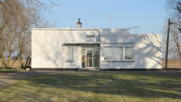
Such was the case for Jim Dalke, contract engineer for KKDZ(AM), a Radio Disney station in Seattle. Fire destroyed most of the Rose Hill main transmitter building in 2005, including the six-tower phasing and antenna monitoring systems. KKDZ 1250 shares the site with KARR 1460.
Insurance covered the hardware replacement; but the need to rebuild the DA monitoring infrastructure presented a unique chance for Dalke and Steve Lockwood of Hatfield & Dawson Consulting Engineers to develop something groundbreaking.
Dalke will discuss their innovation for the legacy AM service in detail at the NAB’s Broadcast Engineering Conference, on Tuesday April 9.
Creative
“When two engineers spend a lot of time on a project, they can get esoterically creative,” Dalke said.
“Discussions included ways to replace the miles of coaxial sample lines and better methods of tuning the array. We considered the possibility of using fiber optics to reduce the costs and improving reliability, plus different ways to graphically display the directional parameters during the laborious and time-consuming phasor adjustments to bring each tower in each mode into licensed compliance.”
Preliminary studies and experiments were conducted at the rebuilt Rose Hill facility in Kirkland, Wash., using one of the KKDZ nighttime towers. A subsequent proof-of-concept project was completed on one tower of the daytime array of KTBK 1210 kHz Auburn, Wash. A complete system is now being installed at the three-tower directional array of KXPA, Multicultural Broadcasting, 1540 kHz in Bellevue.
Dalke chose multi-fiber heavy-duty cable suitable for direct burial to feed the digitally converted tower loop samples back to the phasor and antenna monitor. The cost of the multi-fiber cable is generally less than the traditional heliax type cable used for DA sampling systems, Dalke says.
The heart of this completely digital antenna monitoring system is based on FPGA (field programmable gate array) technology.
“The custom antenna monitor uses the latest high-speed Linux-based processor and employs very fast IOs and bidirectional data buses,” he said. “High-speed A-D converters are installed right next to the tower sampling device outputs and operate at 50 megasamples per second with 14-bit resolution, driving the fiber at a data rate over 700 MHz.”
The FCC rules regulating directional antenna systems currently are based on the use of coaxial cable in the sampling system and analog antenna monitors. With the fiber optic sample system and digital antenna monitor, many of the technical concerns related to cable length and temperature coefficients are eliminated. Another advantage of the fiber optic sample cable is the ability easily to traverse the insulated base of a series-fed tower with high RF voltages present without disturbing the impedance.
Dalke advises, “These advancements in antenna monitoring technology will require revisions to the FCC rules that govern sampling systems and antenna monitors. The new antenna monitor will require FCC type-approval per 47CFR73.53. The design specifications for the new AM should easily exceed FCC performance requirements.”
The fiber optic system is well suited for arrays designed with the new MoM (Method of Moments). Dalke points out, “The FCC rules (73.155) require recertification of the MoM licensed directional antenna every two years to verify the integrity of the antenna sample system. The fiber optic sample system has a function in the digital antenna monitor to calibrate each of the fiber optic sample cables to determine the precise electrical cable delay in real time. This will eliminate the need to manually test the sample cable periodically as required in 73.155.”
Fig. 1 shows a display on the digital antenna monitor representing the relative phase and amplitude of a three-tower array. The boxes represent the FCC limits. Tower 1 is the reference tower. The measured parameters from Tower 2 are out of tolerance and are represented by a red dot. The parameters from Tower 3 are in tolerance and represented by the green dot. The antenna monitor has an internal Web server with Wi-Fi capabilities. This makes it possible to use a laptop or tablet for adjusting the phasor or even making adjustments at the ATU while remotely viewing the directional parameters.