A small battery-powered headphone amp is a useful item to keep in your tool bag or remote kit. It can provide additional monitoring options when the headphone jack on your mixer is already taken or the talent is too far away from the mixer. It also comes in handy when troubleshooting audio gear and you need a quick means to listen to an output. There are suitable offerings available from numerous manufacturers, and the price ranges are just as varied.
But if you’re anything like me, you don’t mind taking some time, maybe getting your hands dirty, and keeping your fabrication skills sharp.
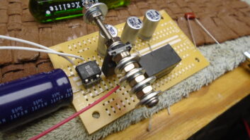
To that end, here’s a simple, easy-to-build, DIY headphone amplifier. It uses some fairly common components, some of which you may already have laying around, and runs off a single 9 V battery. It’s built around the popular Texas Instruments LM386 low-voltage audio amplifier IC. In fact, the basic design comes straight from their data sheet. The chip is designed to run on a wide supply range — 5 VDC to 18 VDC. It doesn’t require bipolar power, so no complicated power supply is needed. Its default gain is 20x, which is ideal for most line-level applications, but that can be increased to as much as 200 if needed. External components are kept to a minimum.

With just a dual-gang log pot, a few capacitors and a couple resistors, all of fairly common values, two LM386s make a good stereo amp. It’s quiet and can faithfully reproduce signals from as low as 40 Hz (the lowest tone my test CD had) to well above what these high-mileage ears can still hear.
As mentioned, the input stage for this build is simply a dual-gang 10 k log pot, creating a variable pad on the input signal. I added a pair of 0.01 μF capacitors between the inputs and ground to shunt any RF that might hitch a ride. The output (wiper) of the pot goes directly to the LM386 input. Some designs I’ve seen online include an additional coupling cap here.

The output of the chip is coupled to the output jack via a 220 μF electrolytic capacitor. Before the signal gets to the coupling cap, it sees a low-pass filter comprising a 0.05 μF capacitor and a 10 ohm resistor. In the various versions of this circuit, some have the capacitor between the resistor and ground, and others have it the other way around. Either way seems to work. In this case, it’s the former. This serves to prevent high-frequency oscillations.
The 9 VDC from the battery passes through a 10 ohm resistor on its way to the supply pin of the IC. This is also filtered through a 100 μF electrolytic capacitor to clean up any oscillations that may appear.

When I first built this amp, I gave it discrete left and right inputs. Then I thought of the possibility of feeding it from a single-channel output, like the aux send of a mixer. Even if I were feeding it a mono input, I’d still want to hear the signal in both ears, without having to use any sort of adapters or splitter cables. As you can see in the schematic on page 24, this was addressed by using a switching audio jack for the right-channel input. A mono signal plugged into the left-channel jack will feed both amplifiers; but if a cable is plugged into the right-channel input, that will interrupt the left channel signal to the right-channel amp and feed it the right-channel input instead. I added an XLR jack, wired in parallel with the left input, to accommodate connections from consoles with XLR sends.

The original build was done using a piece of perf board, but I recently came across a free program called ExpressPCB for creating schematics and PCB layouts. (Regular readers will be aware of how much I love finding free software!) The program is easy to use, and the online help had me setting up a good layout in short order.
Using MG Chemicals’ presensitized positive etch process, I created a small, neat circuit board. Their 3-inch x 5-inch board has more than enough room for three circuits. If playing with corrosive chemicals isn’t up your alley, there’s always perf board, or ExpressPCB will take your layout, created in their program, and fabricate a PCB for a fee.
The enclosure I used is a Hammond 1444-6 4-inch x 4-inch x 2-inch metal box I found in the engineering shop, but any similar enclosure will work. I’ve seen similar builds mounted in old Altoids tins!
Sourcing all the parts from Mouser, the amp can be built for a little over $30; but as I said, most engineering shops may have some or all of these components on hand, making it even cheaper. What’s more, the simplicity of this circuit makes it easily customizable. It’s small enough that it could even be used to add a headphone output to a piece of gear that lacks one. Just power it with a tap from the +12 or +15 VDC rail of the power supply. Because the audio load impedance is rated at 4 to 16 ohms, it can also drive a small cue speaker. By the way, if you’re wondering why mine has a piece of Velcro hook-and-loop fastener attached to the top, I have a corresponding piece attached to the bottom of my copy stand, so I have handy control of headphone volume during VO sessions.
Looking for an extra headphone amp for your audio arsenal? Need something on the bench to check outputs? Or maybe you’re just looking for a “rainy day” project. Fire up the soldering iron and have fun!
Special thanks to my friend and mentor Ron Habegger for checking my work on this project. Even on something this simple, it never hurts to have a second pair of eyes!

Curt Yengst, CSRE, is a regular contributor to Radio World.