Larry Wilkins, CPBE, is director of engineering services for the Alabama Broadcasters Association. This article is part of ABA’s Engineering Academy continuing education series.
Gain structure is a term used by professional sound engineers or FOH (front of house) mix engineers. However, the broadcast engineer should take note of it as well, even in digital operations.
What is gain structure?
Gain structure is exploiting the dynamic range of audio equipment to its best advantage, to minimize noise and unwanted distortion.
All audio equipment adds some noise to the signal, due to the random movement of electrons within the components. This noise is usually very low in amplitude, but when amplifying progressively smaller electrical signals, the noise will at some point overwhelm the sound we are trying to capture.
We need to ensure that the gain in each stage of electronic processing within a signal path is optimized to keep the signal level well above the noise floor, but comfortably below the circuitry’s clipping point.
Optimizing gain structure where several pieces of gear are connected together is even more demanding, as we need to ensure that every circuit is running at its optimum signal level, while still leaving the appropriate safety margin.
The ideal procedure when dealing with line-level signals is a unity gain situation where the signal stays at nominally the same level as it flows from device to device, rather than being constantly attenuated and then amplified, or vice versa.
Ideally the audio level (or video level, for that matter) should stay the same throughout the broadcast plant. You should be able to go to any point in the program path and the level remains the same.
We have mentioned this in previous ABA Engineering Academy articles, but it worth repeating: Start with drawing a signal flow chart for your station; include every device the signal goes through from the console to the transmitter. Next refer to the specification sheet for each device and write down the “clip level” for each one. The lowest clip level for a device in the path becomes your maximum “plant clip level.”
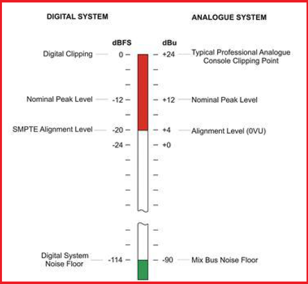
If the maximum plant clip level is +24 dBm, deduct 12 dB for headroom. Your operational clip level will be +12 dBm. Alignment level (using steady state tone) should be +4 dBm (0 vu). Peak audio levels should stay below +12 dBm.
If you are using digital audio, remember that the meter scale is different. Decibel full-scale (dBFS) is a unit of measure for the amplitude of digital audio signals. It is critical to understand: Though digital and analog signals have similarities, their characteristics differ significantly.
0 dBFS occurs when all the binary digits (bits) making up the digital signal are on, or read as ones and not zeroes in computer talk.
All of the bits available to make up the signal have been used at this finite point and no additional headroom exists. Trying to increase the level simply doesn’t work and causes immediate distortion.
Fig. 1 below illustrates the difference between analog and digital reference levels. The digital scale reads in negative numbers with louder, higher amplitude signals moving from a negative number closer to zero. Digital studios should standardize on a reference level of –20 dbfs as 0 VU.
Comment on this or any article. Email [email protected].