We have, in these pages, looked at repack from the perspective of an FM broadcaster, following Doug Irwin on his journey through a repack-forced relocation. Behind every case of a repack-displaced FM station is one or more TV stations being forced to change frequencies, antennas and sometimes towers. In this feature, frequent RWEE contributor John Marcon takes us through a repack experience from the perspective of a television engineer. It is our hope that this will provide insight for repack-TV collocated FM station engineers as they prepare to deal with repack. — Ed.
The winds of change are upon us again. Incentive auction. Reallocation. Repack. Different words with the same meaning to the broadcaster.
Not too long ago, we were figuring out what to make of repack. Initially, there was a feeling that broadcasters were getting pushed around by this gigantic entity known as the Wireless Industry. It feels really bad losing the channel you are long known for and then moving somewhere else. Will the viewers continue watching with the new channel? Will the signal be the same? Are we going off air?
On the other hand, broadcasters are getting brand-new stuff and much more, paid for by the FCC. You can replace anything that needs replacement, as long as the FCC approved of it. True, they will not approve a nuclear reactor, even if you fancy one. However, you can be getting brand-new, top-of-the-line transmitter, antenna, transmission line, cooling equipment, electrical equipment, monitoring equipment, etc. That exchange is not bad at all. It is something you don’t see in a long time or even in a lifetime.
The day came that the repack was approved and the actual auction happened. That was when the real action began. We started the paperwork, then the project planning, scheduling and then the actual implementation of the project.
Two of our stations were to undergo a repack. The new channels are 16 and 18. The first one to be worked on was the station moving to Channel 16.
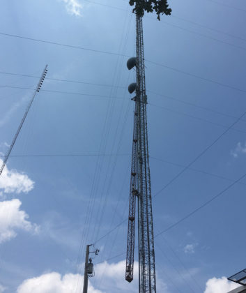
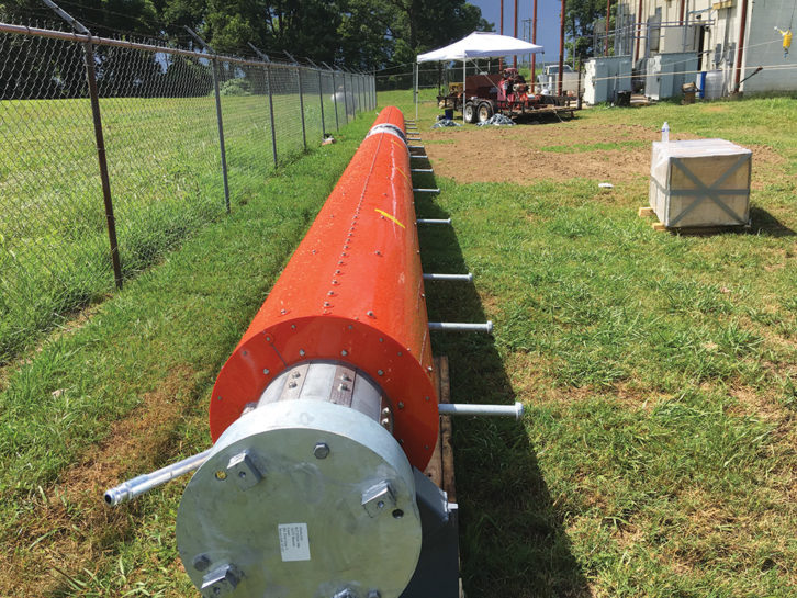
Replacing a high-power UHF antenna is a major project because the antenna alone may weigh 10,000 pounds or more, and it is sitting hundreds of feet up on top of a really skinny guyed tower. We often hire tower crews, and we are somewhat familiar with a number of tower service companies in the south. But if you need to evaluate a tower company, a guideline from TIA can be found at http://wirelessestimator.com/publicdocs/ANSI-TIA-1019-Standard.pdf.
The plan was to install a new main and a new standby antenna. Each would have its own transmission line going into the RF switch inside the transmitter building. The standby antenna was used for broadcast while they were working on the main.
These heavier loads meant added structural reinforcement on the tower. The reinforcing was only done on the lower sections of the tower because that was where all the additional forces were concentrated. They also added new guy wires and guy anchors. This tower was built before 2006 and it is not up to the current TIA 222 G standard. Because of the reinforcement work, the tower was also upgraded to standard G.
After the reinforcement work and the installation of new guy wires and guy anchors, the crew worked on installing the spare antenna and its transmission line. This transmission line was a flexible Heliax instead of the usual rigid lines. The spare antenna was installed about 60 feet from the base of the old antenna.
After that, they started working on the main antenna by first installing a gin pole on top of the tower. This was a slow process because the gin pole itself is like a mini tower. The old antenna cannot be dismantled and the new antenna cannot be installed without the gin pole.
Like any major project work, this one went through some delays. We were expecting a day or two of off-air time, but in the end, the station was off during daytime for more than a week.
SAFETY FIRST
The first thing that somewhat affected the pace of work was an accident that happened on April 19, 2018 at another TV station.
A different tower company, working on another repack project, got into a terrible accident at their job site. The tower they were working on fell down while they were still on the tower, and as a result, the foreman of the tower crew was killed. This happened on a 1,892-foot tower in Fordland, Mo.
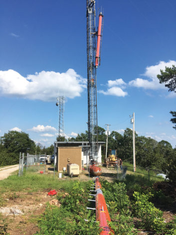
Because of this accident, our tower crew took no chances in every step and made doubly sure that everything was safe and within specs. In fact, instead of taking down the whole antenna at once, they cut it into two pieces so as to lighten the load on the way down and make it a bit easier for the crew and the equipment.
The other thing that further delayed our project was that the upper sections (more than 100 feet) of the old transmission line going up the antenna was in the way of the rigging lines. They had to move these sections of the transmission lines to the side before any rigging could be done. The contractor considered using a helicopter to help in the main antenna installation, but then elected not to.
Another factor that affected the job was the terrain and woods around the tower site. The area is on top of a hill. Two of the guy anchors were down the slope, and the heavy equipment driver had to be extra careful in moving on the slopes to prevent turning over. This would not have been a problem if the terrain was all flat. Thankfully, the large and heavy motorized winch still had a place on the small flat area of the site.

Stations are well aware that tower lighting is a very important safety and regulatory aspect of the tower structure. When the old antenna was brought down, the top beacon was moved from the old antenna to the new one, and we decided to replace the bulb and other parts inside the enclosure. This would hopefully save on tower crew service trips in the future.
The new antenna was raised and installed without a problem. A sweep of both antennas was done, and they were all within specs. Thankfully, after all the tower and antenna work was done, there was no accident or injury. For me, having no incident during this complicated and dangerous job is a major accomplishment indeed.
In theory, the standby antenna should be on-air while the new antenna was being brought down, but this did not happen 100 percent of the time. As you can imagine, to dismantle and lower the old antenna and install the new one, the whole thing would have to pass through the aperture of the spare antenna. The result was that we were not able to use the spare antenna during daytime, only during nighttime and early morning.
From the antenna propagation study, the spare antenna was supposed to have little difference from the coverage area of the main antenna. However, some viewers were not able to receive the signal with the spare antenna. These viewers who used to receive our signals are just a few miles away.
The other thing I noticed was that the old antenna is actually directional (i.e., a cardioid with a small tail), with the main lobe facing away from the target area. This seemed odd, because less signal goes to the target area. Now, the new antenna will just follow this pattern. (The station was built decades ago and I came in only in 2015).
For sure, there must be a reason for this. However, when I asked around, nobody seemed to know why. I learned later that this was done because the area was too mountainous and the signal would just reflect back to the target area, resulting in severe multipath. It was also to protect our main channel from interference. The main channel tower was just 48 miles from this station.
After the work on Channel 16, the tower crew immediately went to work on the other station. Unlike the Channel 16 work, the Channel 18 antenna installation did not have many issues. The reinforcement of the tower was done by a second tower crew. They did an excellent job and, in fact, they had finished the reinforcement even while the other group was still working on the Channel 16 installation.
The spare antenna and transmission line were installed next. They were able to bring down the old antenna and installed the new antenna without any problem. The station off-air days were fewer.
However, once we got on-air, we experienced the same problem of viewers not able to receive our signal. These viewers are just 40 miles from the antenna tower. One thing I noticed is that the beam tilt was increased by 0.05 degrees with the new antenna. The new ERP is also lower than the old ERP. However, upon looking again at the Longley-Rice propagation study, the old and new antenna actually nearly have the same coverage areas. The 0.05 beam tilt increase is needed to achieve this parity.
For the first site, we had an old Axcera 2 kW transmitter which ran at only 1.4 kW. It sometimes had some issues, but by and large, it was a dependable unit. The new unit is a 3 kW Rohde & Schwarz, and it will run at 2.5 kW, which is a kilowatt higher than old transmitter power.
The old ERP was 66.4 kW while the new one is 52.6 kW. It would look like the new ERP was low, but the coverage area would actually be the same. The antenna-transmitter combination was all decided upon based on the FCC-mandated parameters.
The old transmitter was re-tuned from Channel 26 to Channel 16 and was used as the main transmitter.
One thing that was not considered earlier was a directional coupler at the RF output switch. This coupler was needed so that we can have RF power monitoring on the main transmission line and reading for our remote-control system. The coupler will be added later.
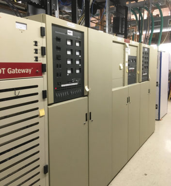
For the second site, we have an old Advanced Broadcast Systems (ABS) IOT transmitter. The brand is not well known but the transmitter proved to be reliable. In fact, the two IOTs ran a whopping 136,000 hours each and were still running until the transmitter’s last broadcast. I believe this is an endurance record for a dual IOT transmitter.
The new transmitter is also a Rohde & Schwarz. The old ERP was 780 kW while the new one is 420 kW. Again, the combination of antenna and transmitter was based on FCC requirements.
For the RF monitoring, a Dielectric RF Scout Monitor Plus was used. The output of this monitor was also used for our remote monitoring system. The new transmitter has its own power meter, but the RF scout is monitoring the power after the mask filter. Thus, it is measuring the actual power going into the transmission line.
KEEP YOUR COOL
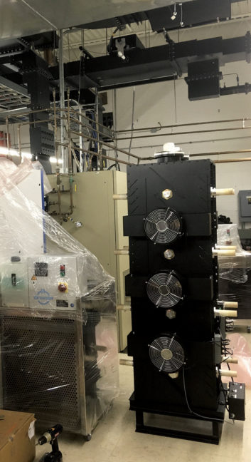 The Channel 16 transmitter site needed a new air-conditioning unit because of the additional cooling load of the new transmitter. The same is true for the other site. It sometimes happens that engineers just pull out numbers from somewhere and then from there decide the size of the cooling equipment. The result is an improper size of AC units. Sometimes even the AC contractor does not know how to size air-conditioning units. Cooling loads must be properly calculated and the units be properly chosen using Manual J and Manual S procedures. You can check with the Air-Conditioning Contractors of America (ACCA) on how to do these procedures. [See “How to Beat the Summer Heat,” RWEE Aug. 8, 2018, or type that headline into the search field at radioworld.com.]
The other thing was calculating the overall electrical load of the site. The pole transformers must be sized big enough to handle both new and old transmitters running. Again, engineers are just used to estimating the actual electrical load of the site using theoretical transmitter efficiencies. This can be a big mistake and, at worst, may cause an electrical fire due to overloaded cables. You need to actually measure the total amperes using a clamp-on AC ammeter, or better yet, an actual AC power meter.
This was our experience and thankfully we did actual current measurements and eventually found out that the capacity of the pole transformers was inadequate to meet the additional load. We ended up replacing the pole transformers. We also replaced the service entrance main breakers and cables. New three-phase power meter, phase-loss sensor and surge arrestors were also installed.
Days before the cutover day, we tested the transmitter and made the proof-of-performance at full transmitter power. The new transmitters were silent compared to our old transmitter. The lack of noise initially felt a little odd. It seems that our senses got used to the noise, and it’s weird when it’s gone.
REPACK TO RESCAN
One thing that I thought about was viewer experience on the day they had to rescan their receivers. Some of us think that rescanning a TV is a simple task, but a lot of folks out there get confused with rescanning their TV sets. There was that chance that we might lose viewers simply because they do not know this process.
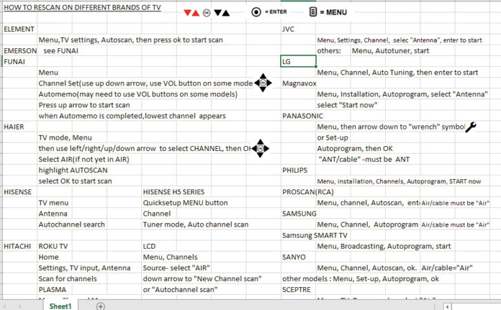
What I did was to list most of the well-known brands of TV and write down their actual rescan steps using the remote. When you go to YouTube, there are actually videos on how to rescan a TV, but they were mostly generalized presentations and would not be of much help. In fact, in some TV brands, rescanning is different from model to model.
So, I thought it was important to look at how scans are done on different brands of TV. The list was distributed among the staff so that they can assist anyone having difficulty with the rescan. Sure enough, there were calls during the cutover day and even days afterwards.
The last lesson came from our GM about the cutover day: Do not say to the viewers that you are “changing channels.” One time, someone asked him about the repack and he said, “We are changing channel and moving to Channel 16.” The person then asked, “Are you taking over the Fox channel?!” He had a lot of explaining to do after that.
Yes, we indeed changed the RF channel, but the virtual channel remains the same. That means that the TV will receive it on a different frequency but will still assign it to the same virtual channel. In a sense, the station did not really lose its original channel.
This repack project is a once-in-a-lifetime experience, and station engineers must be thoroughly involved in it. They need to have a good mental grasp of the nuts and bolts of the project. This will not only benefit them but the network as well.
With as large and complex project as the repack, it is likely that things will not happen according to plan and expectation. The engineers must be aware of this, and they are likely to be asked of critical decisions during the project.
Sometimes contractors, who have done this type of work many times, may fall into a bit of complacency in planning and preparation. It is a concern when they change things on the fly or scribble a technical drawing on the day of the project. With money available for virtually any needed equipment, services and tools, it is reasonable to expect from the contractor the highest quality of work possible.
John Marcon, CBRE, CBTE, 8VSB, is chief engineer of Victory Television Network in Little Rock, Ark.
Read Doug Irwin’s series on the relocation of iHeartMedia’s FM cluster in Los Angeles:
https://www.radioworld.com/news-and-business/the-adventure-continues
https://www.radioworld.com/news-and-business/we-wrap-up-our-fm-cluster-repack-project