The author is a consultant in Carterton, New Zealand. This follows up his December article “Tuned Bandpass Filter Is Solution to Backup STL.”
Many years ago, the active whip antenna and the active loop antenna became popular in AM/MF radio receiving technology, but because they have semiconductor inputs, they have overload points that minimize their usefulness at transmitter sites.
A passive whip antenna can be built and deployed in those situations where the active antennas are not suitable.
THE THEORY
As an antenna gets very short with respect to a wavelength, its resistance component becomes very low, and its (capacitive) reactance increases substantially. Therefore, the antenna has very high impedance and needs to be tuned. When the amount of inductive reactance added in series with the antenna is equal to the capacitive reactance at the desired frequency, a large increase in signal level will occur; the antenna is now resonant.
For example, Fig. 1 shows that a theoretical quarter-wave vertical antenna has a resistance value of 37 ohms and, being resonant, has a reactance value of zero ohms. As the whip antenna we’re building is much shorter than a quarter-wave, the resistance value drops to just a few ohms, and the capacitive reactance increases to several thousand ohms. The short antenna can be resonated or tuned when an inductive reactance is added in series.

At the low end of the broadcast band, many more turns of the toroid inductor will be in circuit, while at the top end, relatively fewer turns will be required. Generally, the losses involved in trying to match the low resistive component of the antenna impedance to 50 ohms are greater than the losses incurred by just ignoring the mismatch!

CONSTRUCTING THE ANTENNA AND TUNING BOX
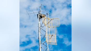
Construction can take many forms. As shown in Fig. 2, one antenna consists of a 5-meter (16-foot) thick-wall aluminum tube mounted on insulators at the top of a wooden power pole. To improve performance, another full length aluminum tube could be telescoped inside to extend the height to 7.5 meters (20 feet). The aluminum tubing is connected to a bare or insulated downlead wire (the wire is still part of the antenna) and terminates on a feedthrough insulator in a small die-cast metal weatherproof box. The other half of the antenna system is a good ground connection, such as the transmitter site’s ground system. Use good quality coax cable, such as RG-213, from the tuning box to your equipment rack in the transmitter room.
The inductors and capacitors are contained within a die-cast metal weatherproof box, and mounted on suitable insulating material. The passive whip makes use of inductors to resonate the antenna at the frequency of interest, which you build by winding wire around and through a toroid. For inductor L3, about 14 feet of 23AWG enamelled wire will make 105 turns around the toroid. For the two smaller inductors, L1 and L2, you’ll need about 4.5 feet of 23AWG wire to make 61 turns, close to the limit for the smaller toroids.
A practical way to wind a toroid is to make a cardboard shuttle that can pass through the center of the toroid. The shuttle will contain all of the wire needed for the toroid; tangled wire won’t be a problem and the wire will retain its position after winding. You can secure the wound toroid with small plastic cable ties.
Inductor L3 is tapped to provide a connection point that is near to the needed reactance. Once the toroid wire is in place, some of the enamel can be scraped off in readiness for a wire to be soldered onto the selected tapping point. A variable capacitor (in series with the inductor) makes resonance adjustment achievable; the difference between one turn and the next being too coarse.
MULTIPLE FREQUENCY OPERATION
The antenna can be used on more than one frequency simultaneously, as long as the various ports are isolated. Parallel tuned trap circuits are effective as isolators, allowing independent reactance adjustment at each receive frequency.
THE CIRCUIT DIAGRAM
Fig. 3 shows the components for outputting two received frequencies from the same antenna. The traps (L1-C1 and L2-C2) are to isolate the tap points, so that tuning adjustments to the f1 output does not affect the tuning of the f2 output. Alternatively or in addition, the trap(s) could be set to the site’s transmitter(s) frequencies. If receiving only one frequency is required, you can omit the traps and just use inductor L3 and trimmer capacitor C3 and take the output from f1.

PASSIVE WHIP ANTENNA PERFORMANCE
A passive whip antenna is suitable for fixed monitoring, for example at a studio, or for off-air rebroadcast at a transmitter site. The recovered RF signal level available at the 50 ohms termination of the antenna is dependent on the length of the vertical portion of the whip, and on the antenna earth system. A 10-meter whip would typically provide, into 50 ohms, a voltage numerically equal to the field strength (as measured in mV/m). For use at a transmitter site, the receiver may need to be preceded by a Bandpass Filter (for details on building a bandpass filter, see “Tuned Bandpass Filter Is Solution to Backup STL,” as noted at the beginning of this article). Good coax cable is required between the band-pass filter and the receiver input.
BEFORE GOING ANY FURTHER
If the receiver’s input is terminated in 50 ohms and there is unintended audio from the on-site transmitter(s) at its output, then it is not suitable without some modification. RF could be getting into the receiver via the mains input or the audio output connection.
SETTING IT UP
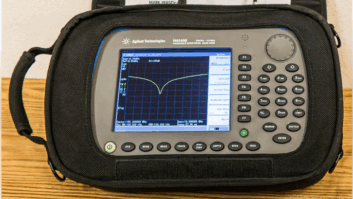
The antenna can be set up with the use of any signal level-indicating instrument. Ensure that there is a 50-ohm load on the antenna system. Set the trap circuits, if used, to their reject frequency by trying different tapping points on the toroidal inductor L1, until a decrease in the recovered signal level is found at the f1 output. Capacitor C1 is adjusted for an exact null. This is repeated for the L2 / C2 / f2 output.
Just like in L1 and L2, tapping points are tried, turn by turn, on the toroidal inductor L3 until an increase in the recovered signal level is found. This increase is usually quite subtle; exact resonance is then obtained by adjustment of the capacitor(s) C3 or C4. The signal peak will be more pronounced with this/these adjustments. Check that the trap circuits are adjusted for maximum rejection, before final adjustment of C3 or C4.
ABOUT THE TORROIDAL INDUCTOR
Fig. 4 shows the inductance versus the number of turns for the two sizes of Amidon -61 toroid cores, using 0.61 mm diameter wire (23AWG). There is a 61 turn limit for the 0.87” OD x 0.54” ID x 0.25” toroid, and a 105 turn limit for the 1.41” OD x 0.90” ID x 0.50” toroid.

At the center of the MW band (1000 kHz), there is a range of reactance of 2,300 ohms (at 10 turns) up to 7100 ohms (at 105 turns). This covers most practical applications.
CONCLUSION
The whip antenna has been used for many years, especially in days long ago when people bothered to install an outside antenna. Today, most listening environments are very noisy, both acoustically and electrically, causing some people to persevere through the noise, while others give up. The antenna described can give excellent results at a MW transmitter site.