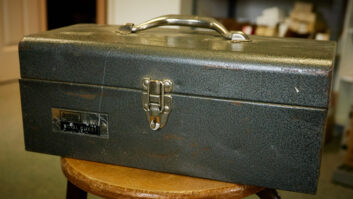
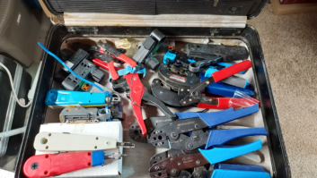
The majority of us laboring in the field of broadcast engineering cluster most of the test gear and techniques that we classify as “useful tools” in the toolbox. Whenever we are faced with a challenging troubleshooting problem or need to make an implementation decision about the best way to install or integrate a piece of gear, we pull out our “tools,” choose the one that is perfect for the job and gather the needed data.
When this effort is on the electric supply side, the most useful test tool is the clamp-on AM ammeter. (You may know it as an amprobe. Once again we have a situation where a dominant manufacturer’s name ends up being used as the vernacular name of a device.
We have seen where Wiremold is a term often used for any surface raceway for wire, while “Xerox machine” is used to describe any plain paper copier. According to amprobe.com, Amprobe was founded in Long Island, New York in 1948 as the Pyramid Instrument Co. and soon was awarded its first patent for the Clamp-on Inductive Ammeter. The company was renamed Amprobe Instrument Corp. The brand Amprobe is now owned by Fluke.)
A TRANSFORMER BY ANY OTHER NAME …
In its purest sense, the meter provides us with an accurate, unobtrusive measurement of current flow past a point in the electrical system. The handheld device is, in reality, a current transformer.
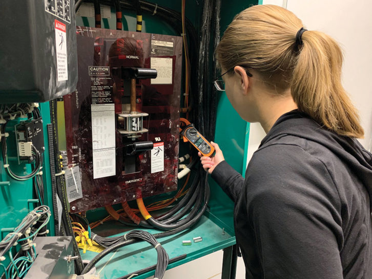
To take a measurement, the jaws are squeezed open and then are placed around a conductor (the primary of our transformer) that the current flows through. Once these jaws (the secondary of our transformer) are fully closed again and the core plates are meshed, a transformer is created such that a very small, proportionate flow of current is induced in the secondary. This small current flow is an accurate analog of (normally) the larger flow in the conductor.
This is very nearly the same way that an electric kilowatt-hour meter that uses CTs (current transformers) measures your electric consumption. A small current analog of the much larger current your system is using is sent to a small current electric meter. An accurate multiplying factor is applied to the recorded value, and that is what the utility bills you for use.
In the clamp-on ammeter, through a calibrated metering resistance, the current can be read on the unit’s small-value ammeter. Analog units feature an appropriate scale; digital units read directly in amps.
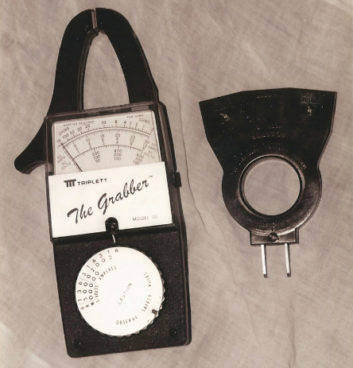
In my real toolbox is my trusty and faithful Triplett unit from the 1970s, the “Grabber.” Dropped, walloped and generally abused, it is still quite accurate and reliable, probably due to its simplicity.
Although Triplett and other manufacturers have improved and enhanced their products considerably since the Amprobe first came on the scene, the basic concept remains the same.
Since we do not have to interrupt the circuit as we do when we insert a direct reading ammeter, the convenience of taking current measurements in this manner cannot be overstated. It’s analogous to taking an X-ray of the lungs when the alternative is to cut open the chest to take a look at them.
BELLS & WHISTLES
The majority of probe units that are available for purchase often have additional multimeter capabilities. Also, it is not unusual for these devices to be further expanded to sample not only the traditional AC current in amps, but also DC amps.
Many of these models with digital readouts utilize onboard microprocessor control, conversion and evaluation circuits. With separate test leads, they often measure AC and DC volts, DC resistance and other useful parameters such as capacitance. This last is useful when troubleshooting motor starter capacitors. With a substitute special test lead probe, my most recent acquisition even measures temperature. Digital units often provide a peak-hold where the display freezes the peak current encountered, which can be a handy feature.
The digital microprocessor enhancement allows readings to be stored in memory for recall or comparison at a later time as well as dynamic integration such that a choice of RMS, peak or harmonic current flow can be read and remembered.
PUTTING IT TO USE
Where and when in your radio station would one of these devices be useful? Here is a short list of a few times I have used my amprobe in recent years:
- I measured the actual current flow on the power conductors to an FM transmitter. The owners thought the electric consumption was much too high compared to the numbers given by the transmitter manufacturer to the station prior to purchase. The numbers I took were typical of overall consumption of this model transmitter. The efficiency percentage given to the station was for RF power amplification alone and did not include exciter, IPA, blower, control circuits, etc. What looked like excessive overall power consumption was actually very good PA efficiency. These numbers settled the argument.
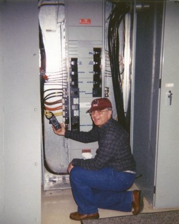
- A station that had its studios in an old house was suffering with very poor computer operation. An amprobe check of the conductors entering the main panel showed tremendous harmonic current on the computer supply line with incumbent voltage drop to the data processing equipment. Running separate oversized supply conductors to the “computer islands” to handle this high current was the fix to eradicate the problem.
- In another case, some sort of intermittent current peak was causing the most unpredictable breaker trips that were taking the HVAC off overnight in a studio. Moving the recording ammeter from each individual unit on the circuit, one after the other, located the culprit that was causing the instability. The probe “remembered” the highest current peak on the wire up to the trip and that isolated the fault.
- In a similar situation, a piece of rack gear was inexplicably tripping its onboard circuit breaker. Letting it run on the bench with the probe inserted downstream of the circuit breaker, we found that the unit was not drawing a 3-amp peak and that it was the breaker that was defective.
Follow the directions that come with your device carefully. With correct use, a major benefit of the probe is that one can avoid close encounters of the electric kind inside hazardous equipment, since you do not have to make direct electrical connection with an operating circuit point when measuring current.
The clamp-on AC ammeter can save you substantial time in troubleshooting and provide extensive, useful and valuable information to enhance the electrical efficiency and reliability of your station.