After my DIY article “Build Your Own Headphone Amp” in the May 25 issue, the good folks at Radio World asked me to share the process by which I make printed circuit boards.
There are usually two phases to the project, depending on whether it’s a circuit of my own creation or I’m using a layout provided by another designer.

At the time of writing this article, Curt was working on a bass guitar tube preamp and a couple of other projects, so some of the illustrations here reference those; however the PCB process is the same. Here is the schematic for that preamp.
It’s inexpensive, which is a plus, since most such circuits are one-offs. What are the advantages to printing a circuit board as opposed to just using perf board or point-to-point wiring? Well, for one, neatness. Would you rather troubleshoot a circuit that has nice, laid-out traces, or a rat’s nest of wires? Also, the layout image can be easily shared with others or archived for future use.

This is what the ExpressPCB tracing program looks like. For this piece I’m working on a bass tube preamp of my own design.
When I’m creating a circuit from scratch, the process starts with a program called ExpressPCB. This free download (www.expresspcb.com) is actually a pair of programs, ExpressPCB and ExpressSCH. The latter is used to create schematics which can then be linked to ExpressPCB. Linking helps ensure that the layout reconciles correctly with the schematic. ExpressPCB uses a drag-and-drop interface, where I can drag component templates into the design, add component numbers based on the schematic, and the program reminds me what needs to be connected to what. When finished, I can print out a copy of the trace pattern.
Now comes the fun part! For creating the PCB, I use the MG Chemicals positive presensitized etch process (www.mgchemicals.com). Their presensitized copper-clad boards are designed to react to fluorescent light. In order to protect the areas where I want traces, I first need to create a positive transparent image of the circuit. This is done using transparency film for laser printers, available from some office supply stores. I put a blank transparency in a laser copier or printer and then print the image.
Next, I peel the protective plastic off the board to be etched, exposing the presensitized etch resist, and I place the film on top of that, covering it with a small sheet of glass to ensure good contact. The glass included with picture frames is perfect for this. Then I place it under a fluorescent light for 10 minutes. I use the work light on my bench. Its adjustable arm makes positioning easy. The light on a magnifying lamp works well too. Any etch resist not covered by the traces will be exposed. While it’s exposing, I get the chemicals ready and put on my rubber gloves.


This is the “transparency” material used to cover sections of the PCB board before exposure to light. Layout patterns can be printed on it in standard copiers and printers.Chemicals, layouts on transparencies and the light-sensitive board are ready to go.


Expose the board and the layouts on top to a fluorescent light.Exposed board is placed in the developer and gently agitated.


Board after it has been “developed.” The etch-resistant material has been removed, leaving exposed copper and etch-resistant circuit traces. Note the multiple projects on a single board.The board is now placed in a container with the actual etching agent and agitated again. The agent removes the exposed copper.
The first chemical is the “developer.” It gets diluted in a plastic or glass pan, 10 parts water for one part developer. Too much developer will ruin the board by dissolving even the etch resist that was protected by the transparency. It works pretty quickly, removing the green etch resist from most of the board, leaving green circuit traces surrounded by bare copper. A quick rinse with water stops the process.
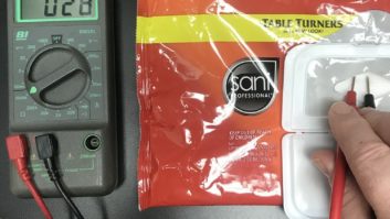
Then, it’s into the ferric chloride etchant solution. This is ready to go right from the bottle. Again, a glass or plastic pan is needed. Ferric chloride is corrosive to metal, smells like burnt rubber, and stains almost everything it touches, so be careful! (You’re wearing safety glasses, right?)
This is the most tedious part of the process, agitating the solution around the board, waiting for the exposed copper to dissolve. Fresh solution works best, and warming it makes it work faster. Warm it by immersing the closed bottle in a large bowl of hot water. It can take up to a half hour to get rid of all the unwanted copper. Another quick rinse with water, and the board is etched.


When finished and dried, the four project modules can be cut out of the PCB and then drilled.A decal was created and used on the unetched side to act as a guide for placing the electronics onto the board.


The finished project is inside this ammo container.The completed board installed inside the preamp.
The final step is drilling the tiny holes for the component leads and mounting screws. A Dremel tool works well for this. An additional step I like to follow is adding a component graphic to the top side of the board. For this I use ink-jet-printable water-slide decals, available from most hobby stores. Now the board is ready to be populated with components.
There are other methods available. I found a couple that involve using either laser-printed trace patterns or special transfer film and a regular clothing iron to transfer the pattern to a bare copper-clad board, then etching using ferric chloride or ammonium persulfate. I’ve even seen examples where the traces were hand-drawn or placed with special stickers. (You try hand-drawing a trace for a 16-pin DIP IC. I’ll pass!)
Etching your own PCB’s can be a great way to give your DIY projects a more professional look, make for an easier build, and also make your designs easily repeatable, especially if you’re making multiple circuits.
By all means, try this at home!
Curt Yengst, CSRE, is a regular contributor to Radio World.
Email us with your own DIY ideas at [email protected]