Ever get a song stuck in your head that you don’t necessarily mind being there? My latest benign earworm happens to be “Frankenstein” by the Edgar Winter Group; probably due to what’s been going on at my workbench lately.
In our first installment, we walked through the audio circuit of “THAT Thing,” a mic preamp design built around THAT Corp. ICs.
POWER SUPPLY
In this “episode,” we start with the power supply. It’s a fairly common, straightforward design. The audio chips require bipolar DC power at a maximum of ±20 Volts. A +48VDC rail is needed for phantom power.
We start with an AC transformer that takes 120VAC from the wall and steps it down to 48VAC with a center tap, 24VAC for each side of the bipolar supply.
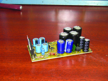
Following rectification through BR1, we get two pulsing DC rails. From there, the pulsing DC goes through a set of electrolytic capacitors, C101-C104, to level out the bumps. Then, the actual regulation occurs with U101 and U102, positive and negative 18VDC regulators. Next, each rail gets another dose of filtering through C105-108 to take out any remaining ripples.
C109 and C110, a pair of polyester capacitors, remove any RFI sneaking in through the power rails. D101 and D102 are there to ensure that the positive and negative rails stay that way. Any negative voltage appearing on the positive rail shunts to ground and vice versa. D103 and D104 protect the regulator ICs by ensuring that the output voltage never exceeds the input.
Finally, LEDs 101 and 102 in combination with their respective current limiting resistors, R104 and R105, indicate the presence of actual voltage on each rail to show that the supply is functioning correctly, a good aid in troubleshooting.
For the phantom power section, the entire 48VAC secondary winding of the transformer is used. After filtering and rectification through C111, C112 and BR2, we’re left with about 70VDC. Additional RF and ripple filtering is accomplished by C113 and C114. Regulation is performed by U103, a TL783 adjustable regulator. R101 and R102 determine the output voltage of the IC, and C116 filters out any output noise.
Additional stability is provided by C115 and R103. 48VDC phantom power must be ruler flat to prevent any noise being introduced at the mic inputs, where the audio circuit is the most sensitive.
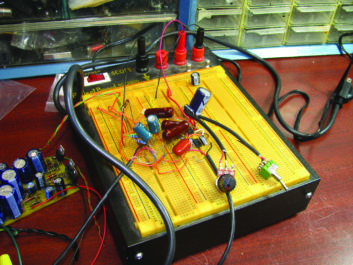
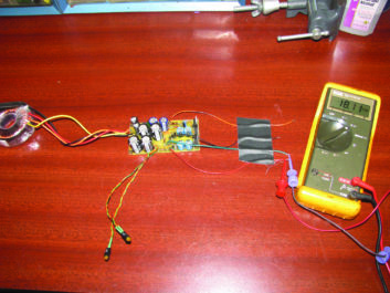
BREADBOARDING
At this stage, I began breadboarding the circuit to test a few component choices and layout. Here’s where I found out firsthand the importance of filter caps C7-C10.
Without those critical components in place, the circuit made a nice white noise generator, especially in the unprotected environment of the workbench!
I also found that I had pretty wide latitude in my choice of C6, the high-pass filter capacitor. I settled on 1 µF because it offered, to my ears, the best balance between getting rid of rumble and being able to go high enough for extreme roll-off, if necessary. Anything — even as high as 47 µF — will work, as long as the gain is high enough.
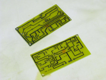
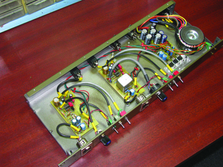
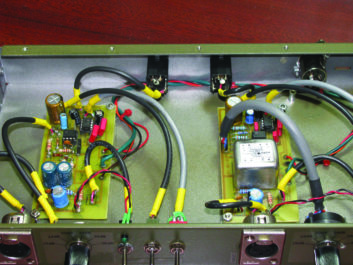
Once I was through experimenting with circuit topology, I imported my schematic into ExpressPCB and worked on the circuit boards. In order to maximize flexibility, and to be able to possibly repurpose the design, I opted to keep the power supply and each audio channel on separate boards.
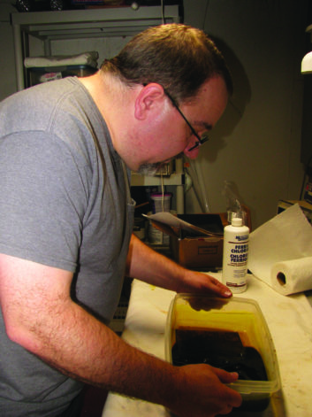
Once I had all the correct parts together and etched the boards, I was able to bench test the finished power supply and one completed channel. Surprisingly, the only issue was that I had wired the phantom power LED on the audio board backwards! An easy fix for a change! It was only mounted directly to the PCB temporarily, anyway. Its intended location is the front panel with the other controls.
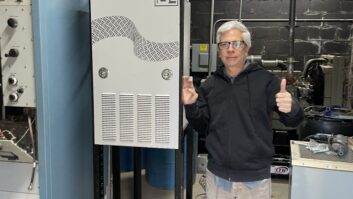
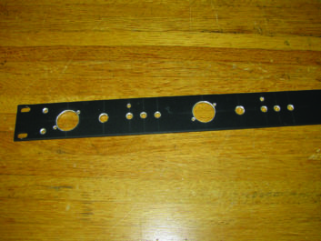
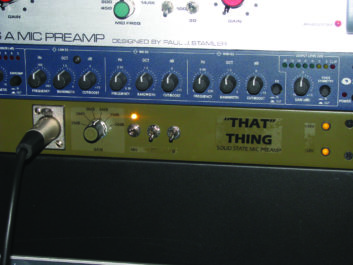
Speaking of which, while thinking about how I was going to house this creation, I came across an abandoned 1RU chassis that was just right. I stripped out the guts and replaced the front panel with a 1RU blank that could be punched and drilled specifically for this project. I put the input XLR jacks on the front panel, taking a cue from a previously built kit in my studio. The output jacks are 1/4-inch TRS for easy interface with my 1/4-inch TRS patch bay.
CONSIDERING IMPROVEMENTS
Never one to leave anything alone if I think there’s room for “improvement,” I started thinking of potential modifications to this design. Looking at some of the design notes from THAT Corp., and discussing this project with other DIYers, I settled on two relatively simple things to try.
First up, an alternative to the gain pot is a rotary switch with several positions, each position providing a different fixed gain. The advantage here is better component matching between channels, which translates to more accurately repeatable settings between channels. High quality reverse log pots of this resistance value can be hard to find at reasonable prices. Besides, more precise adjustments can be made further down the signal chain, or in the mixing/editing stage.
The other modification I looked into was replacing the initial input stage with a transformer. While I suggested in the first installment that transformers are expensive compared to capacitive coupling stages, this is a case where the custom build aspect and its benefits perhaps outweigh the added cost.
 True, the concept behind chips like the THAT1512 is to obviate the need for a transformer, which is perfectly valid, if one is building numerous preamp stages or a 16-channel mixer. On the other hand, a transformer provides way better common mode rejection, kills RFI, eliminates hum loops and also mitigates against any phantom power faults possibly cooking the ICs. Placing a transformer on the input eliminates several other components: C3, C4, R3, R4, R5, R6, R7 and D1-D4 all go away.
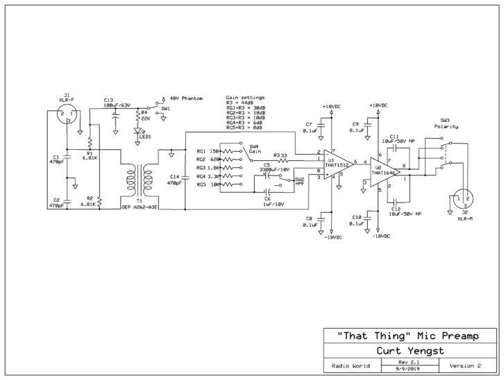
VERSION 2
In version 2 of THAT Thing, I went ahead with the input transformer and the rotary gain switch with six positions.
The transformer I used is OEP’s A262-A3E, which I borrowed from a tube mic preamp in my rack. It’s much less expensive than a Jensen or a Lundahl and, hey, it’s what I had! Good thing it was cheap because while desoldering it from the other preamp’s PCB, I somehow managed to fry the secondary winding. Oops! It had a good run. R.I.P.
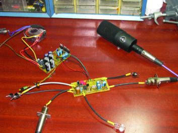
Once the replacement arrived from www.Newark.com, I set about testing it within the circuit. It’s important to consider that the input transformer adds some gain of its own to the circuit, about 16 dB. It took some experimentation to settle on the gain levels for the rotary switch, but I ended up with a range between 19 dB and 50 dB.
So, how did it sound? Super clean, and the transformer definitely adds some character. Either version works very well with just about every mic I tested, from a Shure SM58 to an MXL ribbo n mic, to an Audio Technica AT4040. Two to four channels of “THAT Thing” would nicely compliment a Mackie 1202 or 1402 mixer’s line inputs, should you find yourself running short of mic inputs. Or connect it straight to a PC’s sound card input.
TRY IT YOURSELF
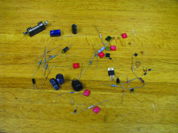
For anyone willing to take a stab at this, I’m happy to provide the schematics, PCB layouts and other notes.
You’ll need to download ExpressPCBPlus (free at www.expresspcb.com) to read and print them out. All parts except the input transformers are available from Mouser Electronics or most other suppliers. The transformers, as mentioned earlier, can be ordered from Newark.com.
Happy soldering!
Curt Yengst, CSRE, is a contributor to Radio World and an assistant engineer with WAWZ(FM) in Zarephath, N.J.
Email us with your own DIY ideas at [email protected].