Over the years I’ve become a student of mic preamp design, building and modifying several along the way and learning a little more each time. Usually, I worked from a kit or published set of plans. Recently, I’ve tried some designs from “scratch,” researching various components, studying earlier designs, and incorporating them into raw schematics, followed by circuit layout, design tweaks and final fabrication.
Since my last two builds were vacuum tube devices, I wanted to do a simple, solid-state design this time. I came across some old preamp ICs in a parts box and almost used them but discovered they had been obsolete for years.
Was there a viable updated replacement? Enter THAT Corp., a relatively small IC manufacturer that specializes in chips for audio applications. THAT makes a few chips that are direct replacements of some popular preamp ICs like the Analog Devices SSM2019 or Texas Instruments INA163. If you’ve ever cracked open a broadcast console, you may have seen one. THAT’s website is a treasure trove of design notes and white papers on mic preamp design, with plenty of ideas to get a project going.
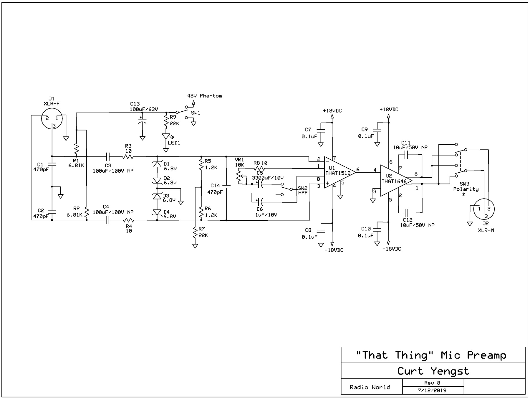
This project uses two ICs from THAT: the 1512 Low-Noise Audio Preamp, and the 1646 Balanced Line Driver. Using design notes from THAT and other sources, including advice from several more experienced DIYers, I was able to come up with a relatively low-cost design that has plenty of gain and good performance numbers for most applications.
The mic preamp can make or break a recording. Aside from the microphone, it’s the first stage in the signal chain before the recorder, and in some cases the only stage. It has to be clean and have ample headroom (unless noise and distortion are your thing), yet have sufficient gain to handle a wide variety of microphones.
Professional microphones have a balanced output, so the preamp will have a balanced input. Normally this is accomplished either with transformer balancing, which is expensive, or by using a standard op-amp as a differential amplifier, usually involving two op-amp stages with their attendant gain feedback loops, etc. The THAT 1512 takes care of this within the chip, providing its own balanced input. All that’s needed is a pretty standard input stage that can provide phantom power. The phantom power is sent to Pins 2 and 3 of the input XLR jack through a matched pair of 6.81K resistors, R1 and R2. These limit the current of the phantom supply.
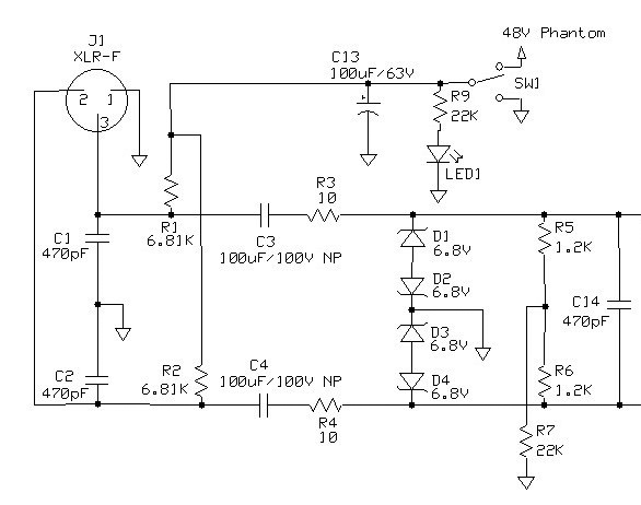
In order to preserve common mode noise rejection, any components that are mirrored between positive and negative signal paths must be matched in value as closely as possible. SW1 [switch] allows for turning off phantom power when it is not needed, and LED1 illuminates to show the actual presence of phantom voltage. R9 limits current through the LED to keep it from going “poof!” Capacitor C13 is there to smooth out any ripples from the 48 V supply. Between Pins 2 and 3 of the input jack and ground, ceramic capacitors C1 and C2 shunt any RF noise that might hitch a ride on the mic cable. Bad mic cables make good radio antennas!
Obviously, we need to keep 48 VDC out of our audio circuit. In a transformer-based design, the transformer would handle this, as transformers only pass AC. Likewise with capacitors, which are much cheaper and take up less space. This is why inexpensive designs use them. The problem is that inexpensive designs tend to skimp on these coupling capacitors. Years ago, I hot-rodded a mic preamp that originally had 4.7µF tantalum capacitors in the coupling stage. I replaced them with nonpolar electrolytics of a much higher value, and performance was improved.
Here, for C3 and C4, I use the same ones. At 100µF it’s overkill, I’ll freely admit, but the higher value reduces low-frequency phase shift (the LF response here is in the single-digit Hz range). Anything around 22µF or greater will work. Besides, it’s very difficult to match capacitors to such tight tolerances.
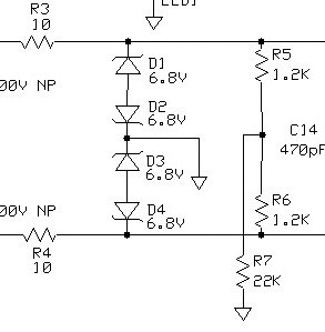
Here’s where R5, R6, and R7 come in. They form what THAT calls a “T-bias” circuit, which boosts low-frequency common mode impedance. C14 is another ceramic capacitor across the inputs to clean up any remaining RF noise. By the way, R3 and R4 are there to limit any fault currents that might sneak by the capacitors. Their low value prevents input impedance issues.
Additional protection from stray static charges and other voltage transients is provided by diodes D1 through D4. This is a simplified version of a number of protection circuits I’ve seen. Anything ugly gets shunted to ground.
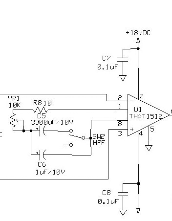
Now, it’s on to the preamp IC, which does the heavy lifting in terms of gain: up to 60 dB of gain, in fact. While a lot of designs will set the chip at a fixed gain level and introduce level controls somewhere between subsequent stages, ours is a simple mic preamp. It would be a simple matter of just inserting a potentiometer (VR1) across the gain setting pins of the chip, right? Not that easy!
Rapid changes in that resistance can introduce DC offset in the chip, which translates to thumping and popping on the output. This is where C5 comes in; a very large capacitor to kill DC offset. Why so large? Because VR1, R8, and C5 comprise a high-pass filter, so the capacitance has to be large enough to bring the low-frequency response down. In this case, it puts it around 5 Hz at maximum gain, keeping any rolloff well below 20 Hz. VR1 is a reverse-log pot, which provides the correct gain vs. position curve.
Speaking of high-pass filters, I included one here to roll-off any mic or room rumble. C6 and SW2 provide a HPF, but this one has a twist. (Special thanks to the folks at www.groupdiy.com for this idea.) Because the changing resistance of VR1 naturally changes the characteristics of the HPF, this filter’s rolloff actually increases somewhat at higher gain settings. At first, this may seem undesirable, but think about it — low frequency artifacts are more likely to be a problem at higher gains than at lower gains. At any rate, C6 is small enough to rolloff the low end, but not to the point of sounding thin.
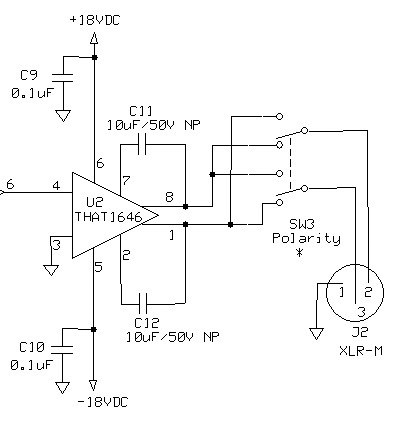
Now on to the output stage, handled by the THAT 1646. It’s one of the simplest I’ve ever seen. One IC and a couple of nonpolar capacitors. Caution must be used if inserting any other stages or components before the 1646, as it is very sensitive with regard to impedance. C11 and C12 are there to address any common-mode DC offset on the outputs. From there, it’s on to the output XLR jack, passing through a simple polarity switch, SW3, to reverse phase if needed.
Finally, capacitors C7 through C10 filter RF gunk out of the power rails to each chip, a very important consideration in any design. Clean audio has to have clean power.
Since this whole thing is built around THAT ICs, I decided to simply call it “THAT Thing.” Tune in next time, and we’ll talk about the power supply, breadboarding the prototype, and putting it all together.
More information about the THAT 1512 and 1646 ICs, as well as design notes and other information can be found at:
• www.thatcorp.com/Design_Notes.shtml
• www.thatcorp.com/datashts/THAT_1510-1512_Datasheet.pdf
• www.thatcorp.com/datashts/THAT_1606-1646_Datasheet.pdf
Curt Yengst, CSRE, is a contributor to Radio World and an assistant engineer with WAWZ(FM) in Zarephath, N.J.
Email us with your own DIY ideas at [email protected].