In the original version of this article, the second figure contained an error. The image has been updated.
It’s important for engineers to have a good, working knowledge of electrical power and, in particular, three-phase service to a transmitter site. I will avoid math here as much as possible and only include whatever math is necessary to increase your working knowledge.
My primary goal is to allow you to speak with confidence to your electrical vendor’s master electrician in order to get precisely what you need.
In this first installation, I’ll discuss the two primary and most-used electrical feeds: three-phase Delta and three-phase Wye, zooming in on the Closed Delta.
Wye
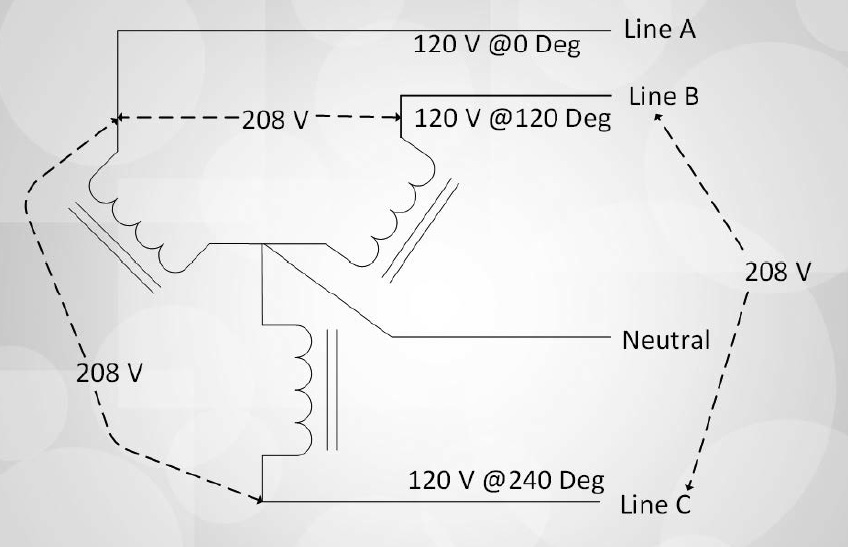
A Wye or “Y” service has several benefits. The first of these is that the center of the Wye is used as a neutral, and single-phase loads can be supplied with any phase to neutral and 208 loads can be supplied between any two phases.
Fig. 1 shows a transformer in a Wye configuration.
Delta
A three-phase Delta is a 240 VAC feed with one phase center-tapped as shown in Fig. 2 to provide two 120 VAC feeds and neutral for single-phase loads.
This type of feed is fine for a transmitter site, and most transmitters can be tapped for 240 VAC use. Note in Fig. 2 that single-phase loads are connected between Phase A and neutral or Phase C and neutral. One must be very cautious never to connect your single-phase 120 VAC equipment between Phase B and neutral — this is 208 VAC!
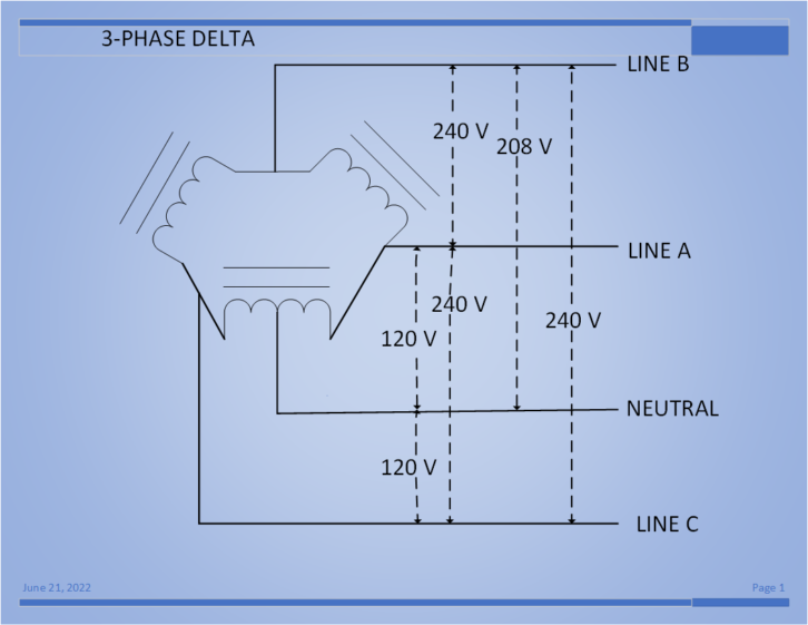
Incidentally, Phase B is often referred to by several names: wild leg, high leg, stinger and bastard leg.
One important note here is if the number of single-phase devices and current draw of your single-phase equipment is high, the transformer winding from which the neutral is derived must be sized larger in ampacity than the other two windings.
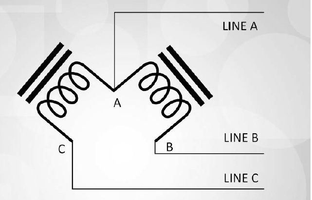
One other note for three-phase Delta feeds: It’s possible to operate in an emergency with one winding missing (so long as it’s not the center-tap winding) and operate in an “Open Delta” configuration, shown in Fig. 3. However, such an arrangement will result in a transformer capacity of 57% (1√3), so loads will likewise need to be reduced accordingly.
By the way, the 57% number or alternatively 1√3 will be seen several times during this series so, memorize it. Its true significance will be shown in the next installation.
Transmitter manufacturers quite rightly warn that an “Open Delta” configuration by virtue of circulating third-harmonic currents present in such a system should be avoided at all costs in order to prevent equipment damage.
There are some other variations of secondary winding configurations such as “Zig-Zag” and “Corner Grounding Delta,” but we will not be discussing these in this series.
One interesting note about the Corner Grounded Delta, about which I’ll bet you may think, “Who uses that?!” When I was in L.A., I was told immediately by the old-timers that the electrical feed at Mount Wilson was a Corner Grounded Delta. I was never able to find out why this was done, but you must remember, this is an old site.
What this meant to the broadcast engineer is that in order to run single-phase loads, an additional single-phase center-tapped stepdown transformer was required at each facility to provide 208 and 120 VAC service. The point is, always specify or at least be aware of the type of service your utility provides.
Closed Delta Secondary Feed
Zooming in on the closed delta secondary feed, refer again to Fig. 2.
Each phase-to-phase voltage such as, B to A, A to C and C to B, are all 240 VAC. We derive a neutral which is joined to ground in the main distribution panel (but NOT in subpanels!) by means of a center tap of the Phase A-C winding, and Phase B is the “high leg” as is dictated by North American Code (at least, generally).
Recall that neutral to the high leg to B phase is 120 VAC x 1.732 (1.732 is 3), or 208 VAC. You and your electrician must be extremely careful not to introduce Phase B to neutral into your single-phase loads (it has happened and that is no balderdash). Most electricians are well aware of this and will not make that error, but to invoke the Russian proverb, “Trust but verify” (Ronald Reagan wasn’t the progenitor of that phrase).
TIP: The best way to deal with avoiding a high-leg concern is to have a three-phase distribution panel feeding a single-phase distribution fed from winding A-C-N (not B) for the 240/120 distribution panel. This eliminates the “High Leg” concern for single-phase loads.
When using such a service, the electrician must be made aware by you of the ampacity required by your single-phase loads (generally you’ll mention this to the master electrician during the bid process). This isn’t just 120 VAC loads, which can be load-balanced between A-neutral and C-neutral, but also consider your 240 VAC single-phase loads such as dummy loads, smaller backup transmitters and blower/circulating fans in your transmitter plant. If these are significant, the A-C winding will need to be sized accordingly or the entire three-phase transformer will need to be sized for worst-case.
As I mentioned, one benefit of the Closed Delta secondary is that if a winding fails, so long as it isn’t the one used for the single-phase loads, you can continue to operate in an emergency mode with a phase missing, which makes this an Open Delta, but at only 57% ((1√3) x 100%). If all three phase windings are center-tapped, you can reconfigure but have the electrician on-site.
Also, the transmitter may have issues due to odd-order harmonic distortion from the Open Delta service — not recommended! As a matter of fact, most transmitter manufacturers will not sell you a transmitter for an Open Delta service, and with good reason!
Current affairs
Now, having discussed three-phase Closed Delta voltages, let’s have a look at currents, both line and phase. This is an interesting topic. Let us discuss in some detail.
First understand that each phase is 120 degrees in phase apart from the other two phases. If Phase A is the reference, then Phase B is lagging by 120 degrees and Phase C is lagging by 240 degrees (or alternatively, +120 degrees versus phase A).
When the circuit is analyzed with trigonometry — which I promised to avoid — the following can be shown. You’ve seen the irrational number 3 mentioned a few times here, which is approximately 1.732 (check this on your calculator). Recall from Kirchhoff’s current laws that the current leaving a node (such as A to B in a delta), is the sum of the currents flowing into the node. In the case of a Delta by virtue of the phase difference, the sum of these currents is not algebraic, but vector addition.
Now, let us say we place our clamp-on ammeter on a line A (junction of phases A-B and A-C) and observe 100 amps. Is this the amperage in the windings? No! The phase A current is the vector sum of windings A-C and A-B. So, not getting into vector analysis, the 100-amp current read by your ammeter in line A is the vector sum of Phase A-B and Phase A-C currents.
Each of these currents is 100 amps / 3, or 57.73 amps. Algebraically, this would be 57.73 amps + 57.73 amps summing to 115.5 amps … but that is not correct. So, in order to be clear, winding A to C is contributing 57.3 amps and so is winding A to B. This will lead to a line current in line A of 100 amps. If the three-phase load is balanced (each line having 100 amps flowing), then 57.3 amps will be flowing in each winding. Note that this condition (balanced loads) is highly unlikely — especially due to the single-phase loads from winding A-C.
Why three-phase power?
At this point, I’d like to deviate momentarily for those new to engineering or new to working with three-phase power. There a few very good reasons for having a three-phase service.
First, by having electrical service delivered in three phases, more power can be delivered to a load with smaller conductors (because each conductor will carry 1√3 of the total load). Also, three-phase blower motors in air conditioners and transmitter cooling induction motors are simpler to start than single-phase induction motors. Single-phase motors require a starting capacitor and a centrifugal capacitor cutout switch in order to start, while three-phase motors generally start with a Wye-Delta starting system (for surge reduction) by virtue of the three-phase rotation. So, if a three-phase motor blows in the opposite direction, you only need to switch two wires of the three-phase feed to correct the blower direction.
In summary, a three-phase Closed Delta is a perfectly fine feed to a transmitter site and has the advantage of pseudo redundancy if a coil or winding is defective and has some advantages for balanced voltages so long as single-phase loads are carefully considered.
In Part 2 we examine the Wye or “Y” configuration and its characteristics. Read that here.