The author is owner-engineer of AM Detuning Service.
Currently there are more than 4,500 AM broadcast stations on the air in the U.S. These stations still rely, to a limited degree at least, on a technology that, at its heart, hasn’t changed much in over 80 years.
One area that uses well-established and core electronic techniques is the AM antenna system.
AM broadcast antenna systems rely heavily on the use of L/C (that is Inductor/Capacitor) networks to accomplish things like impedance matching, phase shifting, broadbanding, frequency trapping, harmonic filtering and numerous other applications.
The most common configuration of L/C components in an AM antenna system is the ubiquitous “T” Network, so named because of the circuit configuration.
[Subscribe to Radio World Engineering Extra]
Nearly every AM antenna system uses one of these networks to match the complex impedance of the antenna to the impedance of the transmission line feeding it. We remember from early electronics training that when the source impedance (the impedance of the transmission line) equals the load impedance (the impedance of the antenna), we get the most efficient power transference to the load. Getting every last watt of power to the antenna is usually good thing!
AM antenna systems have a resistance value (R) and a reactive value (X). Most often, this is expressed as a complex number R+jX.
This complex number is the “impedance” of the antenna system and is measured at the operating frequency of the antenna.
When an engineer designs an AM antenna, its complex impedance can be estimated with a good degree of accuracy using empirical data gathered decades ago, or it can be even more accurately estimated using moment-method modeling. However, ground conductivity at the antenna, variations in the ground radials configuration and nearby structures may have some effect on that value.
The best way to determine the exact AM antenna base impedance is to use an impedance bridge or network analyzer and measure the impedance on the frequency of operation.
Component Arrangement
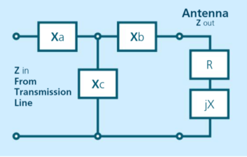
As noted, the “T” network gets its name from the schematic arrangement of the components in its makeup. As Fig. 1 shows, the components Xa, Xb, Xc are electrically connected in a way to form the letter “T.”
For those just getting into radio engineering, I’d like to mention that the components do not have to physically form the letter “T” when they are mounted in place, though they can if you desire. It is wise, though, to mount inductors perpendicular to each other, so they don’t inductively couple energy and do unpredictable things.
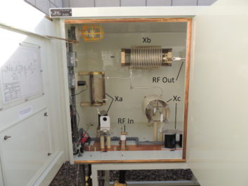
Fig. 2 shows a layout for a commercially-built ATU. You will notice the input component Xa is a capacitor-coil series combination. This coil in series with a capacitor “subtracts” from the capacitive reactance to allow a wide range of adjustment. Xc is the shunt coil of this “T” network, and one end is grounded through a paralleled pair of capacitors. Again, the series coil provides for adjustment of this leg. At the top right is Xb, which is the output inductor. Notice this inductor is mounted at a 90-degree angle to Xc, and in a different plane, to Xa. This is done to minimize mutual coupling between the coils. The component layout may not form the letter “T” mechanically, but electrically it does.
Impedance Matching
One function of the “T” network is impedance matching, that is, taking a high or low value of antenna impedance and transforming it to the same value as its transmission feedline.
Along with the impedance transformation, the “T” network also has some inherent shift of the current from the input to the output of the network. It’s possible to design either a phase-lagging or phase-leading network.
In many, but certainly not all, AM broadcast antenna tuning units, the “T” network is designed for a 90-degree phase shift. The focus of this article will be limited to 90-degree “T” networks.
One of the reasons for choosing a 90-degree phase shift is that this value simplifies the component calculation. The reactance values for Xa, and Xb are the same and Xc is the same numerical value but of opposite sign. Typically, in a phase-lagging network, Xa and Xb are equal value inductors and Xc is a capacitor of the same, but negative, reactance value. The opposite is true of phase-leading networks. But as we shall see, that’s not always the case.
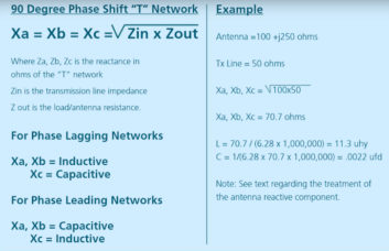
To calculate the values for an example “T” network, the follow the equations in Fig. 3. For the moment, we will ignore the reactive part of the antenna’s impedance and use only the antenna resistance and the characteristic impedance of the transmission line.
In the example shown in Fig. 3, all three component reactances are calculated to be 70.7 ohms, but that doesn’t take into account the reactive component of the antenna impedance. What we need to do is to make that reactive part go away by adding an opposite sign reactance in the output leg of the “T” network.
To do this, we must add a negative 250-ohm reactance to the output leg of the “T” network. This gives us a network that looks like the one shown in Fig. 4.
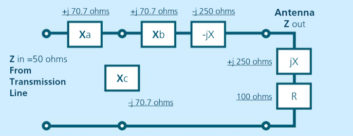
Now we can combine the two reactive components in the output arm of this network into one component by adding Xb + (– jX ) together to get –j 179.3 ohms, which changes this arm of the network from inductive to capacitive. We calculated the capacitor value to replace both of these components to be 888 pF. This isn’t a standard value of transmitting capacitor, so we can either use a vacuum variable capacitor adjusted to that value or employ a standard-value capacitor with a slightly lower capacitance value and put an inductor in series with it. The value of the inductor is then adjusted to achieve the exact net let reactance that we need.
For example, using a 750 pF capacitor and a 10 µH coil, we would adjust the coil for a net combined reactance of –j 179.3 ohms in the output arm of the “T” network.
“T” networks with phase shift values different than 90 degrees require a bit more math. We’ll explore that in a future article.
RW welcomes your Tech Tips, email us at [email protected].
The author started his radio career as an amateur radio operator in his teens and worked for various AM and FM stations in the Chicago region. After 30 years as a chief engineer he retired from radio, got bored shortly thereafter and started AM Detuning Service to mitigate wireless tower effects on AM antennas.