This project was borne out of an odd necessity, a need to install a new rack-mountable transmitter into a rack not quite deep enough to accommodate it.
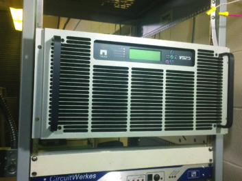
One of my clients, a high school station near Chicago, needed a transmitter, because its old one wasn’t quite capable of attaining the power level needed to meet the terms of a new construction permit. After some fact-finding, the school board settled on a Nautel VS-2.5. The ultimate goal is to put the station on the air in HD Radio, with multi-casting, to provide instructional programming for the local population on the upper HD channels. The Nautel seemed to be the best rig for use in growing that service for the future.
I already knew that the VS-2.5 is rack-mountable, since I had worked with one, and indeed, it comes with a rack slide mounting kit. The depth of the transmitter is about 28 inches (71.3 cm). That’s not counting the length of the necessary cabling hanging out of the back. That’s somewhat bigger than the depth of most racks. Ideally, the depth of the rack should really be 36 inches minimum, in order to be able to accommodate both transmitter and cabling. But the station had no racks that deep and no budget to get one, so we were going to have to make do with what we could get.
Fortunately, we were able to find a solid rack at a low cost to house the transmitter; unfortunately, it was only about 24.5 inches (62.3 cm) deep. But there was little choice here; it was the deepest rack we could find, so we had to get creative with the transmitter mount. It didn’t help that the rack slides were also 26 inches deep at minimum.
My best friend, another broadcast engineer, mentioned that he was doing almost exactly the same thing with another Nautel transmitter at one of his stations, and that the deepest rack he could find on the “pre-loved” market was about 24 inches deep. The mother of invention was conjured up. We had to come up with a way to mount both transmitters reliably in racks not deep enough for either of them.
It took some trial and error, especially error, and a little metal work to bring it off, but we were able to fit the transmitter solidly into the rack, albeit with that little protruding from front and rear. One caveat: The rack slides had to include front-mounted equipment mounting strips.
LET’S GO
Here’s how to do this project:
First, you will need the following materials and tools:
— Four lag screws or concrete anchors, to anchor the rack to the floor or base on which it sits. This is mandatory for the safety of the rack, the transmitter and the personnel who may need to remove the transmitter from the rack for service (plan on that!)
— A set of vertical equipment-mount strips on the back of the equipment rack, drilled and tapped for the usual #10-32 hardware. Not all racks have them, and no rack-mounted transmitter will install properly without their support. If your rack doesn’t have rear mounting strips, order and obtain a pair. Middle Atlantic, for instance, makes them in several styles. Take care in mounting these strips. Use a spirit (“bubble”) level, if necessary, to make sure that the holes on each strip are at exactly the same height. Take care also that the strips are mounted at the same depth and as deep as possible, and that the mounting holes are exactly 19 inches (48.4 cm) apart both top and bottom.
— A length of 1/2-by-1/16-inch aluminum strip. This item can be had from Lowes in 3-foot lengths. You will need to cut it into two 1-foot lengths.
— For a 24-inch-deep rack, four #10-32 x 2-1/2-inch screws, with a nut for each; #10 lockwashers are optional. The screws are available from Fastenal. If the rack is any deeper than 26 inches, the screws can be shorter to accommodate. Beyond a rack depth of 28 inches, this modification will not be needed, as the rack slide mounts will fit into the rack as intended.
— Eight regular #10-32 rack screws
— Four lag screws, at least a 1/4-inch longer than the wood of the base is thick, with washers and lock washers; or cement anchors of a size to accommodate at least 1/4-inch cement lag bolt, and the bolts themselves
— Hacksaw
— Vise
— Drill with 7/32-inch bit
— L-square with movable metal ruler
— Dremel brand tool with #115 metal router bit. You’ll need two bits for this job.
— Two flat files, one course and one fine
— The usual screwdrivers. We used a battery-operated electric with low torque
— Sharpie marker
— Protective gear. Do not neglect this! Safety goggles, gloves and long-sleeved shirt are required to do this job safely!
Here’s the recipe:
— Choose the location for the rack, then anchor it to the floor or riser with the appropriate fasteners.
— Choose the rack location for the transmitter, preferably high in the rack, but no less than 8 inches from the top. This is important because you’re modifying the rack where the transmitter will go, and your handmade support straps will be mounted above the transmitter, topping out at 8 inches above the top of it.
— Assemble the rack slide mounts per the manufacturer’s instructions. For this project, the slide mounts will be completely collapsed.
— Using the hacksaw and the vise, cut the aluminum strip to create two 1-foot lengths.
— Mark the locations of two holes, in the center of each strip, 1/2 inch from the lower end, the other at 2-1/4 inches above that. Use a 7/32-inch drill bit.
At this point, a little discussion about installing the rack slide mounts into the rack is needed.
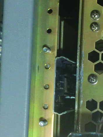
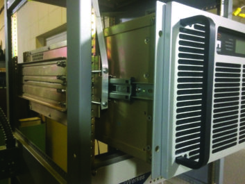
First, the rack slide assembly cannot be mounted without the rear of the assembly being attached to the inside of the rear rack mounting strips. That’s because the back half of the rack mount assembly is strengthened by 90 degree bends at the top and the bottom of the assembly. That lip on both top and bottom would interfere with the strip, making the distance between the slide mount assemblies too small to accommodate the transmitter. As a result, the back of the slide mount assemblies have to be mounted to the inside of the rear equipment mount strip. The mounting screws are started from the inside of the rack, not outside (see Fig.1).
Just as you cannot mount the back support lip of the slide mount to the outside of the equipment mount strip, the same principal applies to mounting the front rack slides as well. This is where the grunt work comes in.
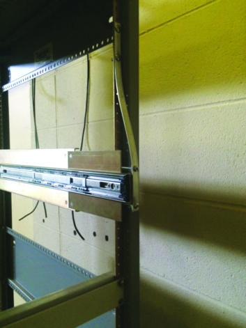
The front portion of the slide mount assembly does not have the 90-degree bends that the rear end does, so it can run past the front of the rack and be mounted such that it is hanging out an inch or two past the equipment mounting strips. However, in order for the transmitter to be mounted at all, the distance between the inside of the two slide mount assemblies must be exactly 19 inches for its entire length. To make a long story short, this will necessitate removing 1/16-inch of metal from each of the front rack equipment mounting strips, in order to accommodate the depth of the metal on the front part of the rack slide assembly (see Fig. 2).
To do this:
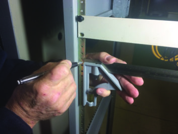
— Set the L-square ruler for a depth of 1/16-inch. It is best to use the metal thickness of the front of the slide mount assembly to set the ruler before you lock it down. On the rack, set the ruler onto the equipment strip, and mark the strip for the depth of the cut. Move the L-square with the marker for a neat straight line. You will notice that, in the end, the cut won’t be so deep on the rack equipment mount strip so as to reach the strip’s mounting holes (see Fig. 3).
— Temporarily mount the rack slide assemblies in the rack and mark the top and bottom of the front end metal, to establish the length of the cut.
— Wearing the safety goggles, long-sleeved shirt and gloves, use the Dremel tool with the #115 bit to ream out the metal on the equipment mounting strips to a point close to the depth of the cut you need to make. There will be tiny slivers of metal flying all around from the cutting area. The safety items I mentioned will be mandatory; you will see why as you work.
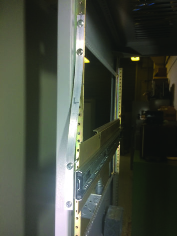
— Use the flat files, course and fine in turn, to square up the corners of the cuts, and to smooth out the rough areas cut to the proper depth all the way up and down. Use the slide mount assemblies to see that the inside edge of the front of the mount fits flush with the edge of the rack equipment mount strip, especially in the corners. You may notice that one of the washers, which is part of the hardware attaching the actual rack slide to the front of the rack mount slide assemblies, interferes with the rack equipment mounting strip. If so, remove a little extra metal at that point on the rack equipment mounting strip to accommodate it. (See Fig. 4 and Fig. 2 again; together they show how the rack slide mount must run flush with the edge of the rack equipment mounting strip.)
— Mount the rack slides to the rack using four regular rack screws in the back, and the four long screws and nuts in the front. In the front, mount the aluminum strips to the outside of the mounting holds on the rack slide mounting assemblies, then thread on a nut on each screw, about halfway up. Then run the screws into the appropriate holes on the rack equipment mounting strip.
— This step will require two people. One person will press the strap up against the rack such that the top of the aluminum strip is flat against the rack equipment strip. The other will use the Sharpie marker to mark the places at which the two holes will be drilled to mount the aluminum strip to the rack.
Note that in all equipment racks, the equipment mounting holes are in groups of three, with the distance between the holes a little greater within the group, but a little less between the groups themselves. We chose to mount the aluminum strips, 2-1/4 inches apart, with the screws going into the first hole above a group, and the first hole below that same group. If you want to mount a 1 RU rack panel at the same point as the aluminum strip, it is better to mark the holes at the top and bottom holes of the group of three, in order to mount the panel behind the aluminum strip.
— Using the locations thus marked, remove the rack slide assembly from the rack and drill two more 7/32-inch holes in each strip.
— Remount the rack slide assemblies into the rack, this time with all the hardware. On the front, if you intend to mount any blank panels to the rack above the transmitter, do it at this time. Note that longer rack screws will thus be needed. Do not over-tighten the long screws on the front of the mount. The tabs on the slide mount should not bend at all. Instead, tighten the nuts to the aluminum strip and the front slide mount front lip, by the screw head. (See Fig. 5)
Then tighten the rear mounting screws — remember, from the inside of the rack (as seen in Fig. 1, again). Finally, tighten the aluminum strips to the rack on the top side.
— It will take two people to mount the transmitter into the rack, per the manufacturer’s recommendations. Believe that. If the job is done right, the transmitter should mount into its rack slides with very little trouble, the first time. With us, it took three times of trial and error to mount the transmitter successfully.
It was this entire collective experience that pointed up the need for this article.
This was the only practical way of which we could think to mount a transmitter of this size and weight in an undersized rack. We were gratified to find that the mount thus created was as solid as could be expected. The size of the #10 screws did not affect the strength of the mount as we thought it might. The aluminum strips, as they appeared, were more than adequate for the task. (See Fig. 6).
My thanks to Clarence Stevens, station manager, for his assistance in this project, and Len Watson, for the motivation, which led to the inspiration.
Art Reis, CPBE AMD DRB CBNT, is a consulting/contract engineer as owner of RadioArt Enterprises LLC in New Lenox, Ill. He is a member of the SBE Education Committee.