There was a time when every broadcast engineer had an oscilloscope for troubleshooting and aligning equipment, from a microphone input to the antenna. It is true that the nature of our plug-and-play world has reduced the requirement for this kind of instrument, but using one can be very helpful in solving problems.
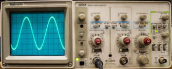
You can literally “see” what an audio circuit is doing wrong on an oscilloscope, while your ears tell you the audio has a problem. My favorite is the Tektronix model 2213A, which is no longer being manufactured. They are sometimes available at hamfests for around $100. There are many new oscilloscopes available on the market for more money.
For those who do not understand or use an oscilloscope regularly, let’s look at the basics.
Follow the trace
An oscilloscope has a display screen, usually a cathode ray tube, with a dot that travels from the left side to the right side and then starts on the left again. This is called the trace.
You can control the speed of this dot with the sweep speed control. There is at least one vertical input to deflect this dot up or down by how much voltage the oscilloscope sees at that instant. My oscilloscope has a 3-by-4-inch screen and is just right for the job.
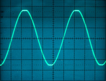
Let’s start with looking at a 1 kHz audio sine wave. By setting the sweep speed to correspond to that frequency, we can see an audio wave standing still on the screen as you do in the photo of a complete oscilloscope. At that point, you can look for distortion and oscillations riding on the wave. The screen has graticules to divide it into equal parts left to right and up to down.
Most oscilloscopes are calibrated so you can use these marks for measuring peak-to-peak voltage on a waveform. Sweep speed is calibrated, too, and can be translated into frequency. The higher the frequency, the faster the dot needs to go to follow the waveform.
[Read past Tech Tips articles here.]
When I work on an analog audio console, I head straight for the calibration controls. Often, announcers hoping for better sound quality on the air have accidentally or mysteriously misadjusted them. I put a 1 kHz tone into a microphone input and adjust the input level followed by the console program amplifier gain until there is just a tiny bit of clipping on the top and bottom of the waveform at the console output terminals.
This is the limit to how much audio the console can produce. Then I reduce the audio input by 20 dB and set the console VU meters to read 100 percent, just before the red 0 to +3 dB portion of the meter display. This gives the classic 20 dB of headroom from 0 VU before clipping starts to occur.
Exact audio output level is usually irrelevant, although it usually comes out to be about +4 dBm active balanced, which is –2 dBm (1.74 Volts peak to peak) on each of the positive and negative audio outputs. With a dual-trace oscilloscope you can see left and right audio channels simultaneously. This is good for setting equal console gain on both channels.
You can watch audio with sine waves or with actual program audio. Follow audio from section to section in an amplifier or place to place in a radio station. You might see the left channel going in the positive direction on the screen while the right channel goes in the negative direction. This is a clear indication that there is a phase reversal in the system that might sound acceptable when listening in stereo, but will sound low level and terrible in monaural.
The key here is that you can actually see what the audio is doing.
AM use
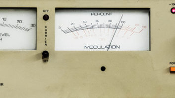
One great use of use an oscilloscope is to set modulation on an AM transmitter. A photo shows about 90 percent negative modulation when voice program audio has depressed the carrier to almost zero at times. You can also see that positive modulation at the top and bottom of the display is being limited or clipped.
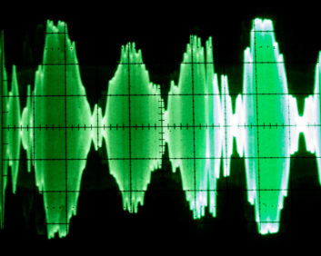
Modulation monitors can and do go out of calibration. The display on an oscilloscope cannot lie. If an oscilloscope shows 100 percent negative modulation with the carrier going to zero along the horizontal centerline, you should believe it.
I employ an oscilloscope on the service bench when adjusting an RF generator for 100 percent AM modulation and then use that RF to calibrate modulation monitors. No laboratory standards are required. The method is simple and doesn’t get any better than that.
In conclusion, an oscilloscope always went with me on the road to radio stations when doing updates and repairs. It continues to be an extremely important test instrument on the service bench. I couldn’t do the job without one.
Mark Persons, WØMH, is certified as a professional broadcast engineer by the Society of Broadcast Engineers and has more than 30 years experience. He has written numerous articles for industry publications over the years. His website is www.mwpersons.com.