Almost every engineer has had the opportunity to top off his or her vehicle’s air conditioner with a can or two of R131A refrigerant. But don’t throw the empty can away — with a little work, you can turn it into a notch filter.

Fig. 1: Don’t throw this can away — it’s a notch filter waiting to be constructed!
Newman-Kees consulting engineer Frank Hertel recently encountered a few sites that have experienced RF interference to their 900 MHz digital mode STL receivers. To correct the problem, Frank and his team have been using notch filters to attenuate some of the interfering signals from the cell equipment. Most of the problems were due to the strong cell site transmission overloading the front end of the receiver.
While Frank was topping off the refrigerant in his truck, it struck him that the refrigerant can would lend itself to becoming a notch filter, thanks to its dimensions. Filters at these frequencies are interesting — they are basically hollow canisters with a tuned probe or stub protruding into the canister.
The pictures here illustrate the process that Frank used to build his notch filter. It turned out that (by pure luck) the “as built” notch fell at 815 MHz.
By lengthening the stub, which was a small piece of brass hobby tubing, Frank could move the notch down to about 650 MHz. Shortening the stub permitted Frank to move the notch well above the 900 MHz band.

Fig. 2: Tools you’ll need to construct the notch filter.

Fig. 3
Frank notes that if the cavity was made of 1 5/8 inch or 3 1/8-inch hard line, with appropriate connectors and properly optimized, it could remedy the needs for higher-power transmitters that have harmonics in the cellular bands.
Keep in mind that this do-it-yourself filter has not been optimized. This results in the notch being fairly broad. But this is a good thing, in the case of notching out the cellular bands. The notch will reach a depth of approximately –30 dB. Its insertion loss at 940 MHz is approximately 3 dB.
In this particular case of using an R134A can as the cavity, the length of the stub is the key factor in the cavity’s notch frequency. The diameter of the stub will be instrumental in the bandwidth and depth of the notch, while also influencing frequency. Remember that everything interacts.
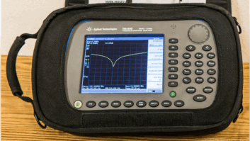
Readers will need access to a spectrum analyzer that has a tracking generator in order to “tune” and “know” the specs of your notch filter, otherwise you are flying blind.
This is an easy build, go ahead and build it because you can. Figs. 2 through 8 will take you through the construction steps.

Fig. 5

Fig. 4

Fig. 7: Thread the BNC connector and stub assembly onto the nut.

Fig. 6
Frank hopes this project will be useful; you might even come up with another use for an empty R134A can in the process. If you do, share your results with Workbench!

Fig. 9: The notch filter specifications.

Fig. 8
Contribute tips. You’ll help fellow engineers and qualify for SBE recertification credit. Send Workbench ideas to [email protected]. Fax to (603) 472-4944.
Author John Bisset has spent 46 years in the broadcasting industry and is still learning. He handles West Coast sales for the Telos Alliance. He is SBE certified and is a past recipient of the SBE’s Educator of the Year Award.