I sold low-power FM transmitters in a former job, and one of the things I learned is that most customers lacked a suitable dummy load for testing. In new LPFM or translator applications, you can save a lot of time if you have a way to confirm proper operation.
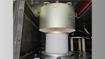
Remembering the days of the Heathkit “Can-tenna,” which mounted the necessary load components in a paint can, I contacted RW contributor Buc Fitch, who frequently describes useful modifications and upgrades in our pages. Buc recently developed a dummy load of his own that mounts in an empty quart paint can (the kind of can you can buy at Lowes or Home Depot).
Fig. 1 shows the needed parts. Visit your hardware drawer for brass bolts, washers and nuts. You’ll also need 15 dual-hole solder lugs for the resistors, using five for each of three layers, with two resistors on each lug. A total of three single-hole lugs will also be needed. These tie the center pin and ground connector leads to the resistor stack. (Head to radioworld.com/links for a URL for solder lugs from Digi-Key.)
You’ll need 30 dummy load resistors — 1.5k-ohm, metal film, 2-watt resistors soldered in parallel. You choose the RF connector; type N or UHF female are the most common and flexible. You’ll need a small 3/8-inch rubber grommet, to serve as a vent, as well as about two feet of #18 tinned solid wire.

Sort your parts and you’re ready to go. Here are the steps:
1. Take a long, 4-40 brass bolt and slip five dual position solder lugs onto the bolt moving them up against the bolt head. Thread a 4-40 hex nut onto the bolt and spin it down until the five solder lugs are snug.
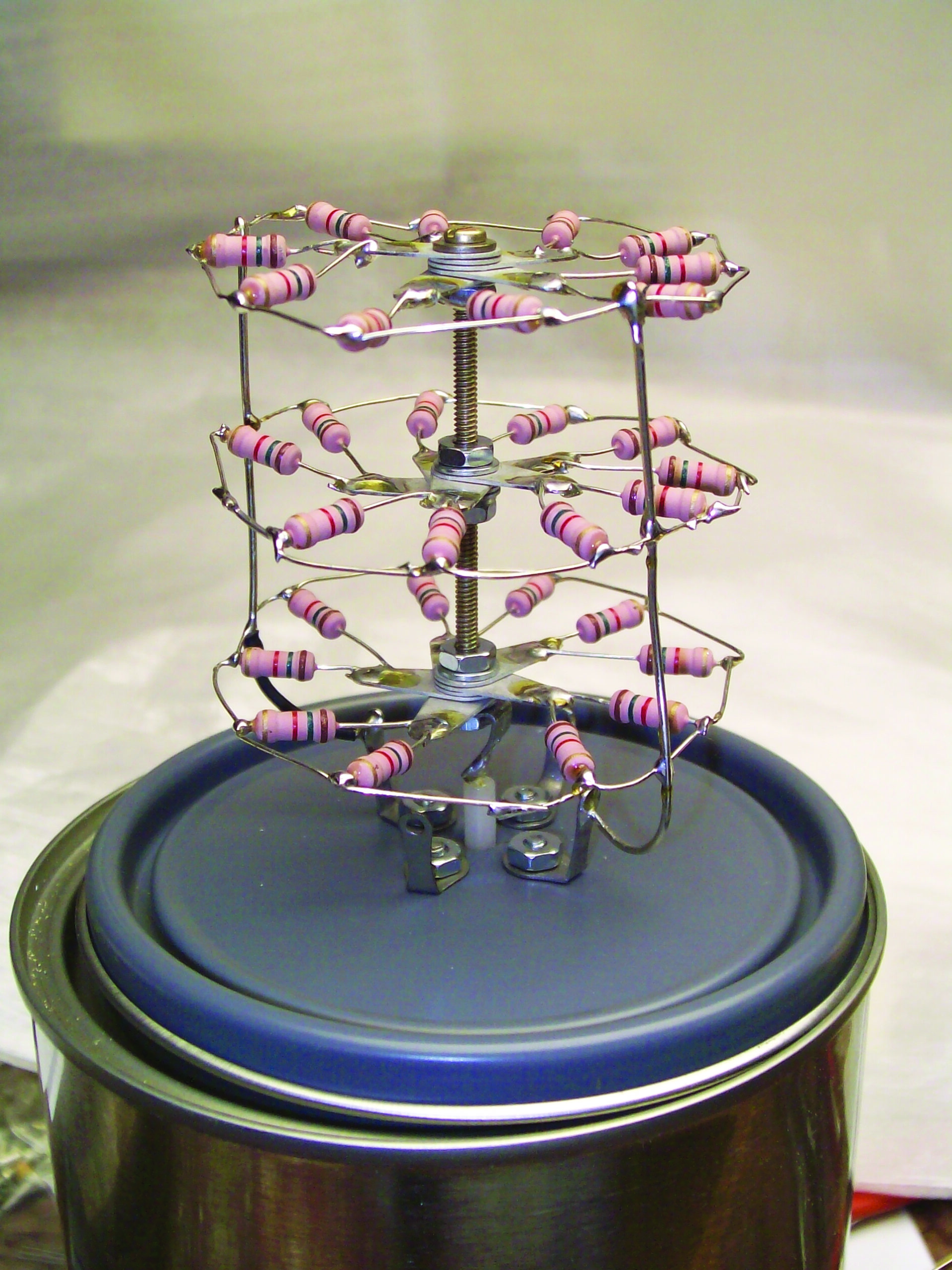
2. Position the five lugs into a “star” configuration, with each lug offset in an approximately 72-degree azimuth. Refer to Fig. 2 to see what this looks like.
3. Holding the lugs roughly in position, tighten down the nut. Select two of the thirty 1.5k-ohm, 2-watt resistors, confirm that the leads are clean by scraping each resistor leg with a razor blade knife until they shine. Cut off one end to a 1-inch length, and 3/4-inch length on the second.
4. Mechanically attach the two resistors through the lugholes by bending the short end at 90 degrees. The lead with the 3/4-inch length should be attached to the far hole and the 1-inch lead to the solder hole nearest the bolthole.
5. Position angularly as indicated in the photos and solder the resistors to the lug.
6. Bend the uncut end in imitation of the assembly in Fig. 2, such that a common circular “ring” will be created when all 10 of these resistors are soldered together.

7. Solder the tip of the 1-inch cut resistor to the 3/4-inch cut resistor.
8. Repeat this procedure on the next lug in clockwise rotation and continue through the next three lugs until all 10 resistors are installed.
Important: Even with the best effort, sometimes there is insufficient lead length to make a perfect common circle. Use small pieces of the bus wire to complete a uniform, even and professional-looking circle.
9. Thread a 4-40 hex nut onto the bolts, and spin down to just about 3/4-inch from the bolt head.
10. Slip five dual position solder lugs onto the bolt, moving them to the end against the nut threaded in Step 9.
11. Thread a 4-40 hex nut onto the bolt and spin down, until the five solder lugs are snug.
12. Once again, position the five lugs into a “star” configuration with each lug offset in an approximate 72-degree azimuth pattern.
13. Rotate this lug cluster so that it is positioned with the lugs between the first set and, holding the lugs roughly in position, tighten down the nut.
14. Repeat Steps 5 through 11 above on this set of lugs.
15. Thread a 4-40 hex nut onto the bolt and spin down to just about 1-1/2 inch from the bolt head.
16. Slip five dual position solder lugs onto the screw moving them to the end against the nut threaded on in Step 12.
17. Thread a 4-40 hex nut onto the bolt and spin down, until the five solder lugs are snug.
18. Once again, position the five lugs into a “star” configuration.
19. Rotate this lug cluster such that it is positioned with the lugs in-line with the first set and holding the lugs in position, tighten down the nut.
20. Repeat Steps 3 through 8 above for this set of lugs.
21. Choose a place on the outer circle nearest the bolt head between the resistors and attach a length of bus wire about five inches long.
22. Route the bus wire on the outside of the middle resistor group circle and inside the final circle common section.
23. Solder the three connection points on the three circles. See pictures for routing detail.
24. Repeat Steps 21 through 23 on the opposite side of the common circles.
25. At the very end of the bolt, thread a 4-40 hex nut onto the bolt and spin down to just about 1/4-inch from the bolt end.
26. Slip a single solder hole lug onto the bolt.
27. Thread a 4-40 hex nut onto the bolt and tighten.
28. Measure the diameter of the center assembly of the chassis-mounted female N connector.

29. Select a drill bit and drill a hole into the center of the lid to accommodate the connector.
Important: The can is very thin sheet metal; for optimal results, mark the hole using a small drill bit such as 1/8-inch. Using this first hole as a guide, progressively and carefully enlarge the hole until the hole is the required size.
30. Insert the connector and mark at least two of the four holes. If only two are used they should be diametrically opposite.
31. Drill the holes for 4-40 bolts (approximately 1/8 inch in diameter).
32. Mark the top for the “breather hole,” which should be eventually 3/8-inch. This hole should be approximately 1 inch from the lid outer edge.
33. Drill out the hole for the rubber breather grommet progressively, as outlined above, for best results.
34. Mount the RF connector using a 4-40 nut/washer/and bolt. Place a solder lug under the two diametrically offset bolt positions mentioned above.
35. Bend down the solder lugs under the connector.
36. Bend the one single position lug at the end of the bolt into a half circle such that the open lug hole will mate with the wire end of the N connector, position the bus wires such that they are in line with the connector solder lugs and solder.
37. At this point the crenellated resistor assembly is attached to the connector at a single point, so carefully thread the two common bus wires through the connector lugs and solder in imitation of the pictures.
38. Cut off excess bus wires. The unit is complete.
39. Distilled water may be used as a coolant for testing and measurement but empty the dummy after each use to limit rust and deterioration. Mineral oil is a good permanent coolant; just keep the load upright so no coolant escapes the breather vent.
40. Enjoy your dummy, but always make certain that there is coolant in the can, the lid is on tight and the breather unclogged.
Buc measured this load flat out to beyond the 160 MHz RPU band, with a power handling capacity of 50 watts. The parts for the load cost about $20.
Thanks, Buc, for a great project.
Contribute to Workbench. You’ll help your fellow engineers, and qualify for SBE recertification credit. Send Workbench tips to [email protected].