Ever since a young Henrich Hertz began constructing the scores of electrochemical cells needed to power the world’s first radio transmitter in the 1880s, designers have sought out better and more efficient ways of providing the required voltage sources for transmitters.
Today, it’s not that big a deal; you just hang some diodes on the output of a power transformer, add some electrolytic caps and maybe a choke or two if you want to be fancy, add a pre-packaged regulator, and you’re in business. Actually, the power supply of a modern radio transmitter is probably one of the most reliable parts of the whole machine. Nobody gives them much thought at all anymore.
But it wasn’t always that easy.
The history of the lowly transmitter power supply — from its humble (and sometimes complicated) beginnings to the compact, quiet, cool-running and efficient package of today — is full of interesting twists and turns. In this two-part article, we take a look.
Hertz’s primitive battery was sufficient to power the spark oscillator he constructed to prove out Maxwell’s equations, and this set the scene for everything that was to come.
(click thumbnail)
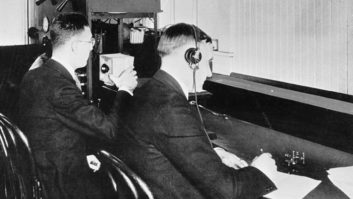
Loy Barton’s initial 500 watt KUOA 1924 transmitter design used a mixture of power sources: a motor-generator set for plate voltage, a battery for bias and a conventional AC step-down transformer to light tube filaments. However, hum problems forced him to replace the transformer with another motor-generator set to supply DC to the filaments. Credit: James O’Neal collection Following on the footsteps of Hertz, Guglielmo Marconi began experimenting with “low-power” transmitters and finally reckoned it was time to scale things up and perhaps put wireless technology on a paying basis. He was responsible for the first really “big” transmitter, which was completed in 1901 in his attempt to span the Atlantic by radio. And like many future engineers, Marconi ran into some power supply problems.
Ambrose Fleming had been hired as a consultant to help with the design and construction of the large transmitter needed, and came up with a “double-decker” spark oscillator powered by an AC generator. As with most new technology, things didn’t work that well right out of the box.
Fleming’s notes indicate that some amount of time was spent in experimenting with circuit configurations to try to optimize performance. He went for a true “smoke test” on at least one occasion, noting that “large resonance effects” were suffered by the alternator, with its windings smoking from the RF being fed back into it.
Fast-forward a few years to Marconi’s commercial radio service between Cape Breton, Nova Scotia, Canada and Glace Bay, Ireland. A hybrid DC generator/storage battery configuration replaced the earlier alternator as a power source. This consisted of three series-connected 5,000 volt generators tied to a storage battery made up of 6,000 two-volt cells, each rated at 40 amp/hrs. The fully charged batteries alone could power the spark transmitter for quite some time, as the total capacity was approximately 500 kWh at 12,000 volts of very pure DC.
However, that was “spark,” and as such didn’t have much entertainment value for the general public. AM transmitter technology began to evolve for transmitting speech and music, and with it came additional requirements for direct current power.
AM radio
The Poulsen arc or “arc-phone” transmitter was the earliest device that could be used to modulate a carrier with speech and music in a practical manner. Charles Herrold in 1909 used arc technology to become the first broadcaster on the West Coast. According to Mike Adams and Gordon B. Greb in their book “Charles Herrold, Inventor of Radio Broadcasting,” Herrold met the high-current DC demands of his transmitter, and keep operating costs down, by “borrowing” power from a 500 volt streetcar catenary that was conveniently located near his station.
When the broadcasting craze broke in the early 1920s, many individuals were vying to get a station on the air, and as “old-line” radio transmitter companies didn’t exist, this led to some unusual designs (and sometimes very steep learning curves).
One of the biggest problems was in powering those first generation broadcast rigs. Notwithstanding the DC plate potential required for the RF power tubes, high-current DC was also needed for filament power, as virtually all tubes then were designed with DC filaments.
(click thumbnail)
These motor-generator sets powered the University of Arkansas’s KUOA for several years. They were located in the basement of the school’s “Old Main” building, with the transmitter situated four stories above and feeding a roof-top antenna. Credit: James O’Neal collection Providing pure hum-free DC was a real challenge.
As a work-around, at least one early station ran its transmitter strictly on storage battery power: KJBS in San Francisco. The station even made on-air announcements plugging the Willard Storage Battery Company, according to an account by John Schneider on the bayarearadio.org website.
Rectifiers with moving parts
One of the most intuitive and well-developed methodologies for converting AC to DC was via rotating machinery — motor-generator sets.
An AC motor of suitable size was coupled to one or more DC generators to provide plate, grid and/or filament voltages. Only a minor amount of filtering was required, and “stock” units could generally supply the DC power requirements of very early broadcast transmitters.
Actually, the motor-generator set became the de facto standard for delivering transmitter DC in the decade of the 1920s and on into the 1930s. Initially, units designed for other applications (typically electrified light railway service) were grafted into transmitter power supplies. However, as transmitter size (power) increased, catalog motor-generators were no longer adequate, and at least one manufacturer created a special division to supply transmitter manufacturers and individuals constructing their own rigs.
This was necessary, as the motor-generator sets developed for streetcar and interurban rail lines rarely required potentials above 1,500 volts. By the mid to late 1920s, transmitter builders were demanding machines that could deliver upwards of 18,000 volts.
Motor-generators for radio service were special in other ways too. While some amount of ripple current didn’t bother the light rail industry, even a slight amount of voltage perturbation could cause problems in transmitters.
“If the generator does not commutate without sparks, these sparks will cause pulsations in the voltage, which will also produce audible sounds in the transmitter,” Westinghouse engineer J.H. Blakenbuehler observed in a detailed 1928 article on his company’s work in producing motor-generators for radio work. “Those pulsations producing the most annoying sounds have frequencies between 500 and 2,000 cycles per second, with probably the most distressing tone occurring at 1,100 cycles per second.”
Blakenbuehler also expressed concern over the effect of minute voltage changes on transmitter frequency stability. At that time, many transmitters consisted of little more than a power oscillator stage and modulator. There was no crystal control to keep things steady, and slight changes in plate potential could cause frequency shifts (as could the change in capacitance due to the station’s flat-top or cage antenna being blown about by the wind).
“Generators with poor regulation have been known to vary the signal frequency so much as to cause the reception by a heterodyne receiver to be very difficult,” Blakenbuehler cautioned in an obvious pitch to tout the superiority of his company’s products.
The very high output voltages and output stability necessitated a complete redesign of existing motor-generator products, with some of the Westinghouse devices for broadcast service requiring six miles of wire for the armature of a four-pole generator, and an additional two miles for the field coils.
Factory testing methods for these high-voltage motor-generators had to be modified too. According to Blakenbuehler, ordinary carbon resistor loads used for testing lower voltage generators proved too expensive and unsafe, so another type of load had to be developed: the water barrel rheostat.
(click thumbnail)
Water rheostats were used as a load for testing high-voltage DC generators intended for radio transmitter duty. This Westinghouse device actually “burned” water in normal operation. The flame at the top is due to the spontaneous recombination of hydrogen and oxygen generated by the electrolysis effect on the water being pumped into the unit during operation. This device, shown in the accompanying photo, was essentially a hollow porcelain tube, with an electrode (anode) positioned inside. The other electrode was a stream of water (probably made conductive by addition of a weak acid solution) that was connected to the generator’s negative terminal. Water flowed into the tube, completing the circuit and presenting a load to the generator.
Blakenbuehler noted a “peculiar” phenomenon experienced when such a load was tried with very high voltages.
“The current density at the cathode was evidently so high as to decompose the water into hydrogen and oxygen, which recombined in a flame at the surface of the water.” The “burning water” is evident in the photograph.
Conquering AC hum
In 1924, radio pioneer Loy Barton became a motor generator customer, specifying a motor-generator set for the plate supply of the 500 watt broadcast transmitter he designed and constructed as part of the requirements for an advanced degree at the University of Arkansas.
His thesis reflected difficulties with powering the school station’s transmitter, primarily AC hum problems.
Barton was so perplexed that he wrote engineers at most of the stations on the air then to find out if they had hum problems and how they licked them. The consensus was that if hum was to be avoided, in addition to pure DC for plate potentials, transmitter tube filaments also needed fairly pure DC. (Of the 70 stations polled by Barton, approximately 50 responded, with the overwhelming majority saying they had to resort to DC for lighting filaments.)
Barton reasoned that the hum occurred due to a very slight physical movement of the large filament structure in power tubes at a 60 cycle per second rate, thus creating hum modulation of the signal.
(click thumbnail)
As the size of transmitters grew, some installations resembled power generating stations due to the use of motor-generator sets for providing DC voltages. This photo shows part of the equipment room associated with WOWO’s first 50 kW transmitter, constructed in the late 1920s. (Curiously, the station never operated it beyond 10 kW, only going to 50 kW operation in 1954 with a much more modern transmitter.)
(click thumbnail)
Perhaps the most famous transmitter using motor-generator sets was the WLW 500,000 watt machine that went on the air in 1934. Three 1,500 amp devices were used to power the filaments. Credit: Charles Stinger
He initially tried several schemes to null the hum component, but none proved really satisfactory and he eventually ordered a 15 volt/100 amp motor-generator set for transmitter filament power.
As broadcasters opted for higher and higher transmitter powers, Westinghouse and other suppliers of broadcast-type motor-generator sets were kept busy churning out new designs to meet the requirements of the larger tubes being employed. In photos of installations from that era, some station transmitter facilities look more like electrical power stations than broadcast operations.
One of the most famous of these was WLW. The station’s 1934 makeover into a 500,000 watt facility initially required 20 of the huge UV-862 100,000 watt tubes, each with filament requirements of 207 amps at 33 volts DC. At the time of construction, the only practical way to supply the 4,140 amps necessary was with a motor-generator set. WLW actually had three 1,500 amp monsters, each driven by an 85 HP motor and installed in the basement directly under the transmitter. They were paralleled together with copper bus bars resembling small HVAC ducts.
James O’Neal is technology editor for TV Technology and a frequent Radio World contributor. Comment on this or any article. Write to [email protected].