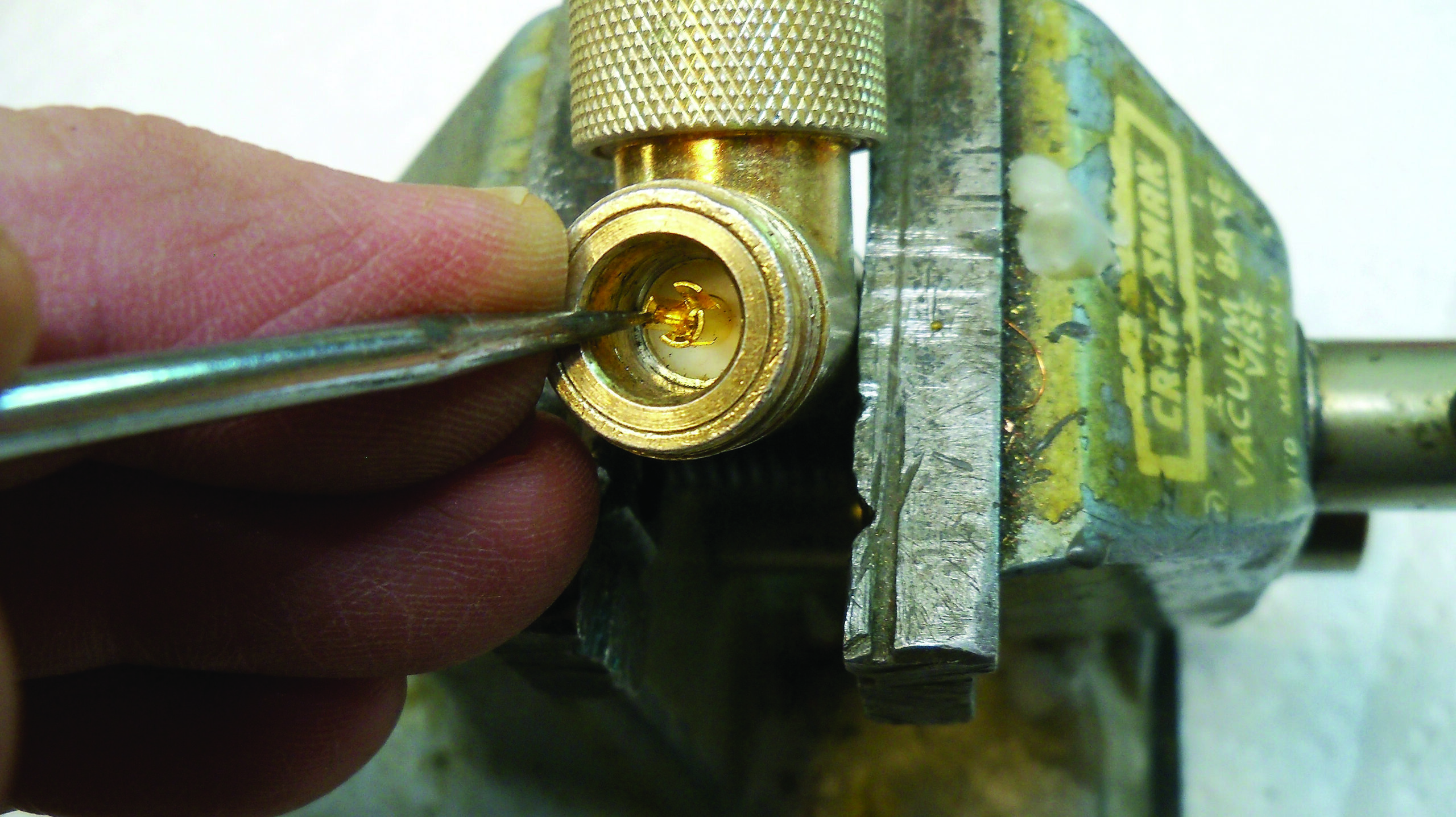
It’s happened to all of us: The center pin of a Type “N” connector gets deformed, as seen in Fig. 1. The resulting poor connection can be frustrating. As Murphy’s Law would have it, there is no spare connector or pigtail to use as a replacement.
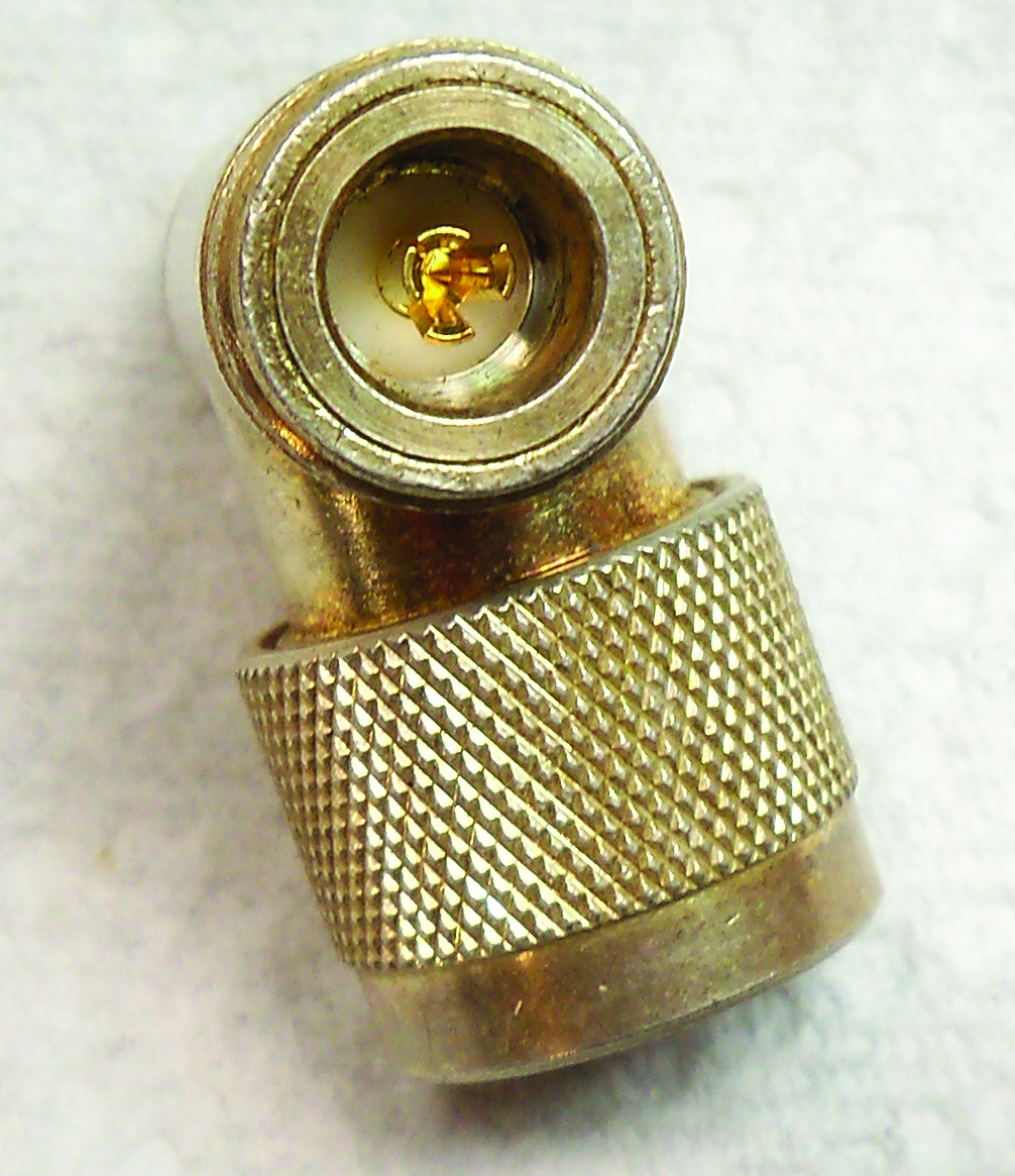
Frank and Dave Hertel, principals at Newman-Kees RF Measurements and Engineering, have a great solution to the problem, so don’t throw out the connector just yet.
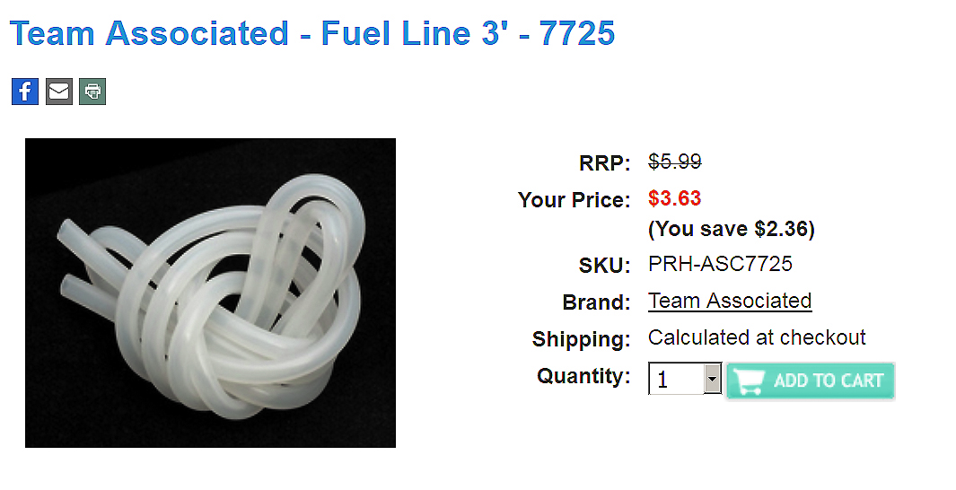
If the center pin flanges are not broken off, merely bent, a package of plastic fuel line costing less than $5 may correct the problem (Fig. 2). Cut several 1/4-inch pieces and store them in a resealable container. Contract engineers in particular will want to keep several of these on hand.
The next step is to bend the splayed contact fingers slowly and carefully back into shape. It’s important to take your time. Use a dental pick or similar fine-tipped instrument to coax the spring fingers gently back in place. If you are aggressive, you will break the fingers.
Make the bends in very small increments (demonstrated in Fig. 3). If you are patient and wait 10 to 15 seconds between each small bend, you will have a better chance of reforming the center conductor fingers.
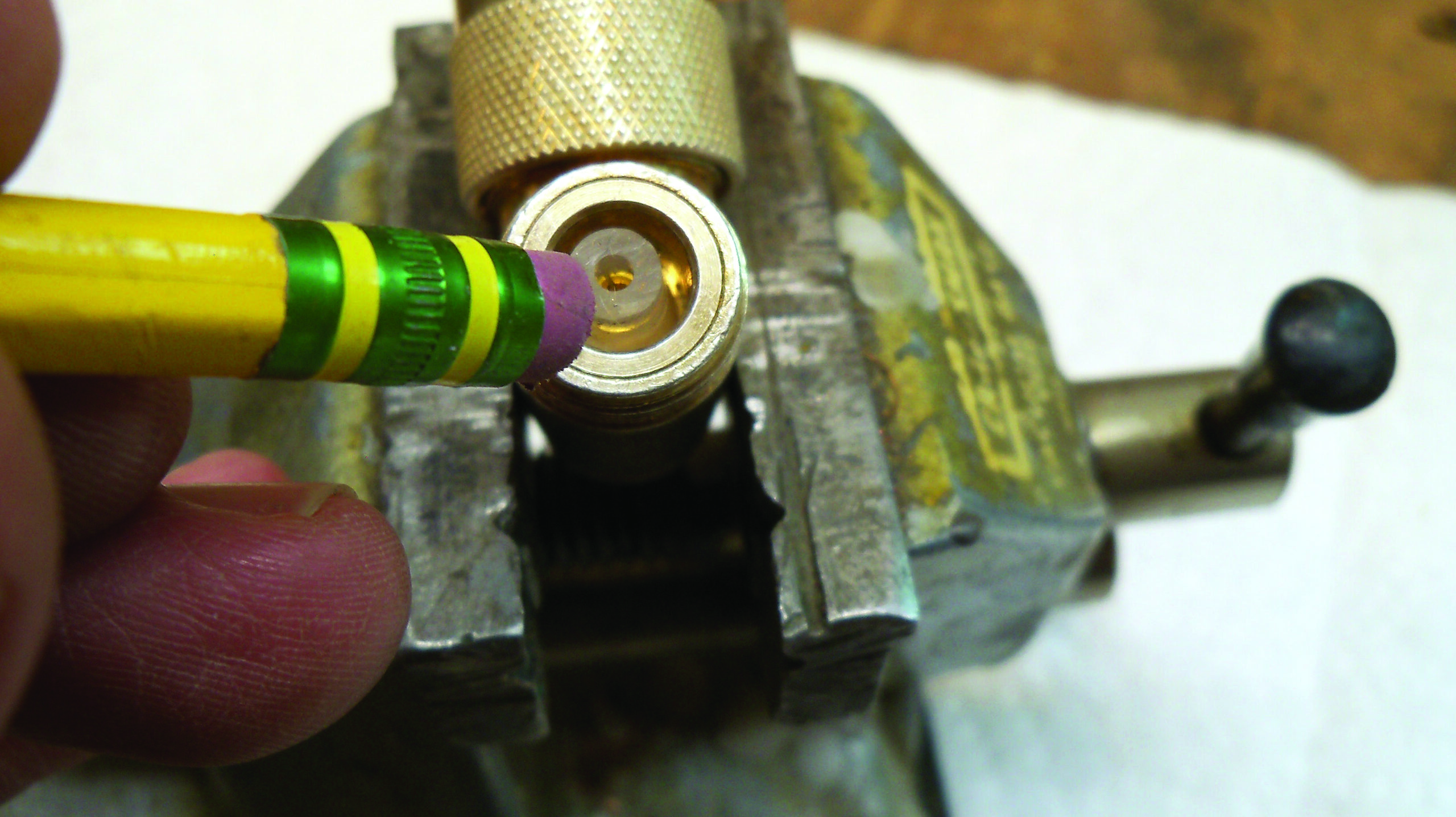
Once the fingers are bent back into position, you need a way of keeping the fingers snug around the center pin of the corresponding connector. That’s where the 1/4-inch piece of silicone fuel line comes in. Slip it over the center conductor fingers. A pencil eraser is the ideal size to press the silicone fuel line sleeve over the fingers, as seen in Fig. 4.
Frank and Dave recommend using these sleeves on new connectors and jumpers as well. That’s why you’ll cut a number of these 1/4-inch pieces and keep them in your tool box. Slip the sleeves over new connectors during installation to guard against damaging the connector.
There’s another benefit: dealing with water damage. One of the biggest problems with STL type “N” jumpers is the ingress of water. Over time, a good weather-proofing seal can go bad. The resultant moisture entering the connector can reduce signal level.
The Hertels say that their experience shows adding this little sleeve greatly reduces the moisture problem. The silicone gas line sleeve acts as a water barrier, should moisture enter the connector.
There is no need for concern regarding signal loss or mismatching of the system using the silicone gas line. Within the 950 MHz range of the STL spectrum, no mismatching or losses have been measured or noticed. Since you buy the silicone gas line in three-foot lengths, you might think it will last a long time.
As soon as your engineering friends and associates see what you are doing, they’ll ask for a 6-inch or 1-foot piece to cut their own 1/4-inch sleeves. If you’re looking for an SBE meeting activity, buy a length of line and some polybags, and snip a bunch of sleeves for everyone to use.
Frank and Dave used Team Associated Fuel Line 3-7725, found at www.activepowersports.com for less than $5.
Thanks guys for sharing this useful tip. Contract engineers can use it as a fee-added or a value-added service for clients. Chief engineers will find that this sleeve provides peace of mind for all their Type “N” connections.
Nearly all the new studios I’ve seen recently being planned and installed have specified at least one Henry Engineering Multiport.
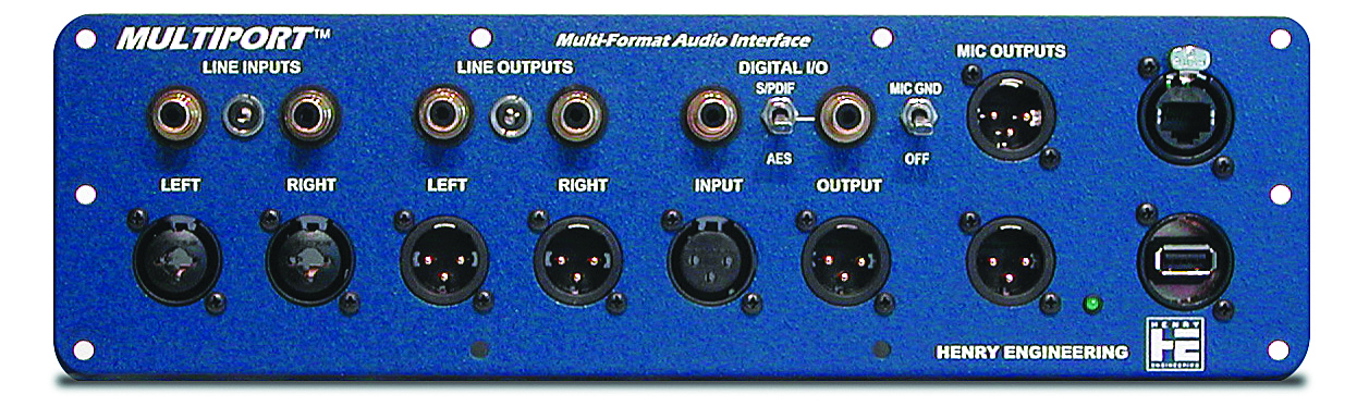
Seen in Fig. 5, the Multiport is an interconnect panel that facilitates the interface of external audio equipment to the studio for both analog and AES/EBU connections. Also called a world feed panel, this product permits interconnection of both broadcast professional and consumer gear to the studio console. Multiport also provides two “pass-thru” connectors for easy access to USB and RJ-45 circuits.
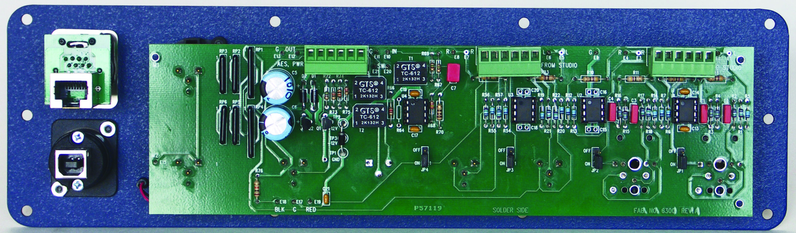
The USB connector is reversible; either the square or rectangular jack is available on the front panel. The rear of the Multiport is seen in Fig. 6. Contact your favorite broadcast equipment dealer for more information.
Contribute to Workbench. You’ll help fellow engineers and qualify for SBE recertification credit. Send Workbench tips and high-resolution photos to [email protected]. Fax to (603) 472-4944.