Newman-Kees Principal Consulting Engineer Frank Hertel says a friend recently brought him an old LPB 30-Watt AM transmitter for repair. It’s a good low-power transmitter, but this one had been abused.
Once Frank had it repaired, he needed to verify its output power and modulation. He decided to use his oscilloscope to accomplish both verifications. That’s Frank’s preferred method but his friend had never done this and was interested in the process. It’s a procedure worth considering, especially when other verification methods might be wrong due to miscalibration. Frank shares the process with Workbench readers.
You don’t need an RF ammeter or power meter, just a dummy load or a 50-ohm antenna that you know is good. The process requires that your AM transmitter is operating into a 50-ohm load with zero reactance.
Several notes at the outset:
- For AM transmitters of 250 Watts or less, you can connect directly to the transmitter’s RF output; but for the safe of safety, be sure to use a 10x (times ten) oscilloscope probe. This also assumes you honor the oscilloscope probe and ’scope voltage limits.
- Again, for safety: When working with AM transmitters operating with more than 250 watts, connect your oscilloscope’s 10x ’scope probe only to a calibrated sample port of at least –20 dB. Failure to do this will damage your oscilloscope!
- Remember that when a transmitter is fully modulated, the peak-to-peak voltage of the transmitter’s RF output will be twice the level of its unmodulated RF output!
- To protect your oscilloscope and your 10x probe, always verify that both of them are capable of handling the high RF voltages that will be presented to their inputs when the transmitter is modulated at 100%.
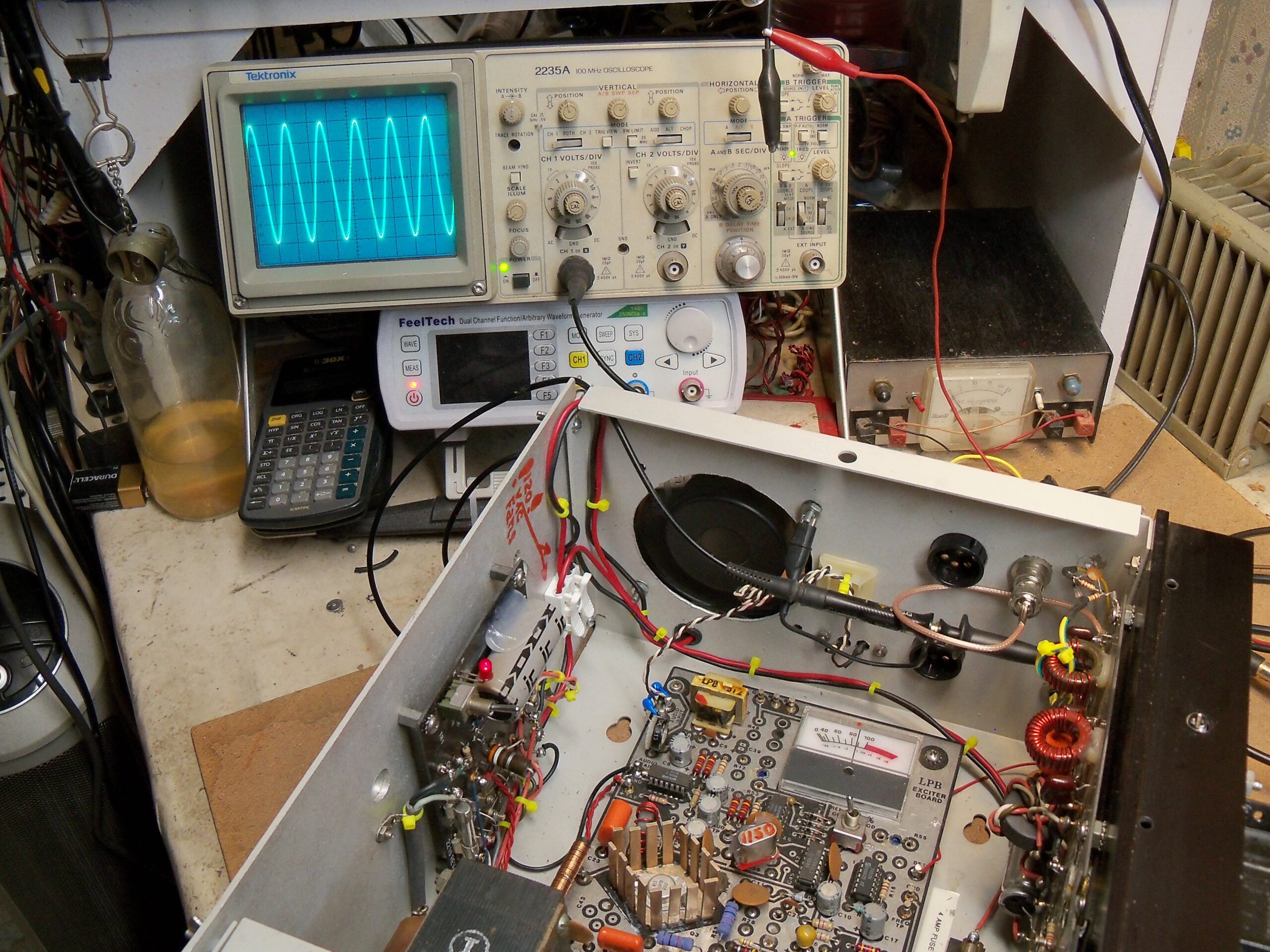
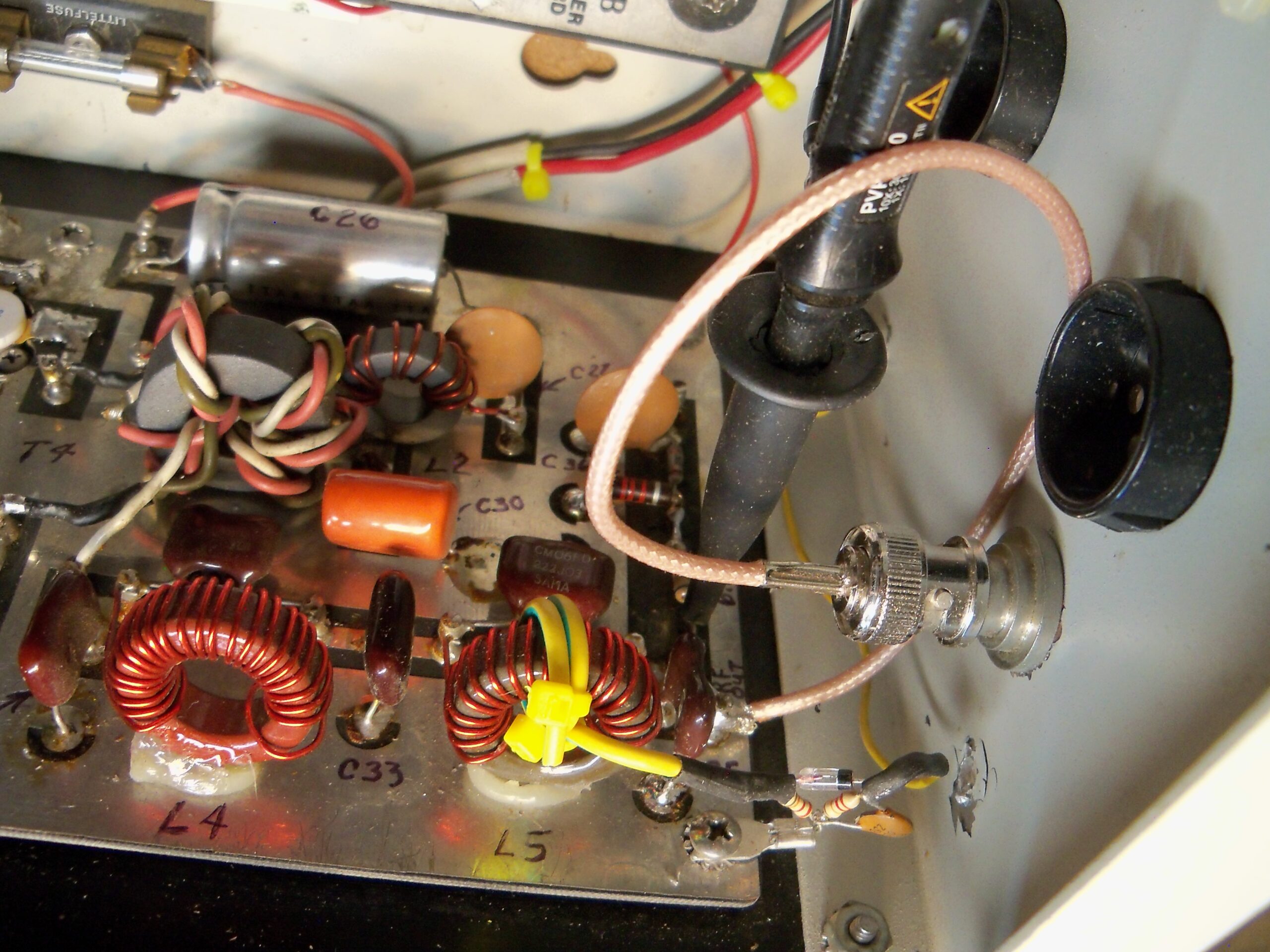
To proceed: With the transmitter AC off, connect the ’scope probe as shown in Fig. 1. Make sure the RF output is terminated in a known 50-ohm dummy load. When you apply AC power to the transmitter, you should see an oscilloscope display similar to what’s pictured in Fig. 2.
In this case, the ’scope has been set to display 20V per reticule, and our figure shows 120V peak-to-peak. This is the unmodulated RF carrier. Note that Frank has expanded the view of the RF carrier to check visually for any distorted carrier wave or harmonic content.
Using this 120V value, you can calculate the transmitter power output using the formula 120²/400=36 Watts.
You are squaring the peak-to-peak voltage displayed on the oscilloscope, then dividing that number by 400.
The transmitter is indeed making power and can be trimmed, using the power adjust potentiometer to a licensed 30W.
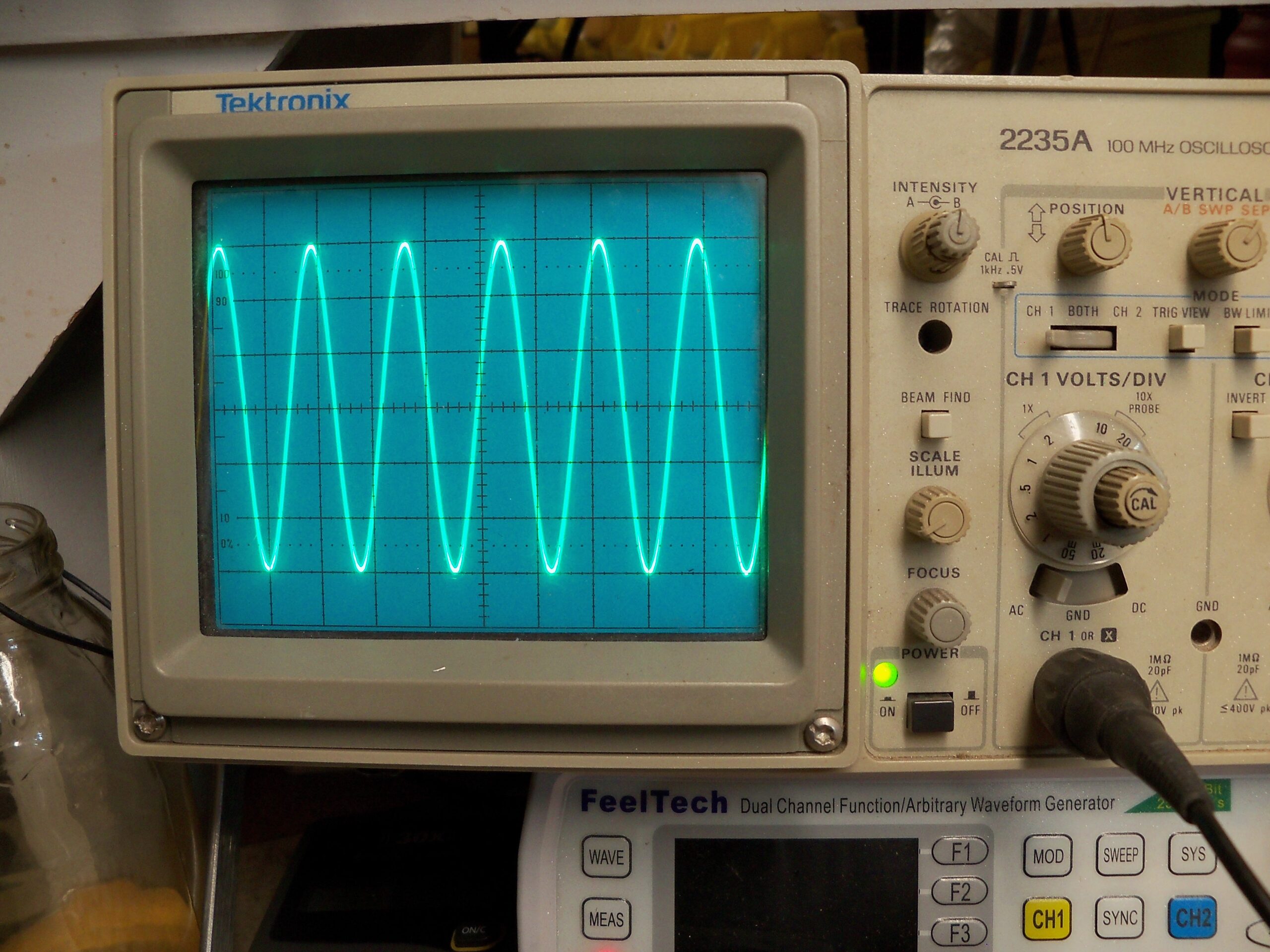
Now it’s time to check the modulation level. In Fig. 3, Frank displays the 100% modulation on the left, comparing it to the unmodulated carrier on the right. Remember that 100% modulation occurs at carrier “pinch-off.”
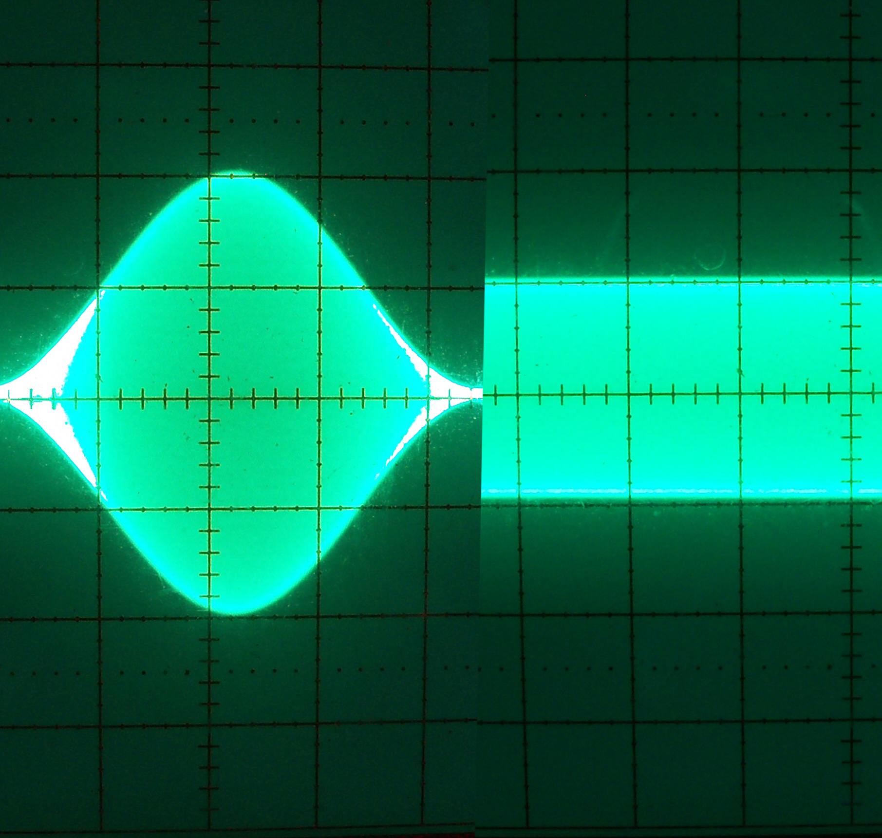
You’ll also want to remember that a 100% modulated carrier yields double the voltage level of the unmodulated carrier. Also keep in mind that when the RF voltage is doubled (at 100% modulation) that the RF power is four times the value of the unmodulated carrier. This is defined as peak envelope power or PEP.
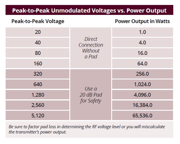
The accompanying table compares peak-to-peak unmodulated voltages and power output. Look at how much power is generated when the peak-to-peak voltage is 5,120. Broadcast engineering is not for the faint of heart!
On another note
I recently noticed that both the beacon and the side obstruction lights on a newly erected cellular tower were flashing. Are you aware that the FCC now allows this change to save birds?
Apparently migrating birds are attracted to steady-on lighting but avoid flashing lights. Before I could investigate, frequent Workbench contributor Dan Slentz sent a link to an FCC publication that describes the issue and offers a solution. In addition to saving birds, there’s a power-saving benefit that should appeal to managers and owners. Visit www.fcc.gov/guides/towers-and-birds.
Tips please! Workbench submissions are encouraged and qualify for SBE recertification credit. Email [email protected].