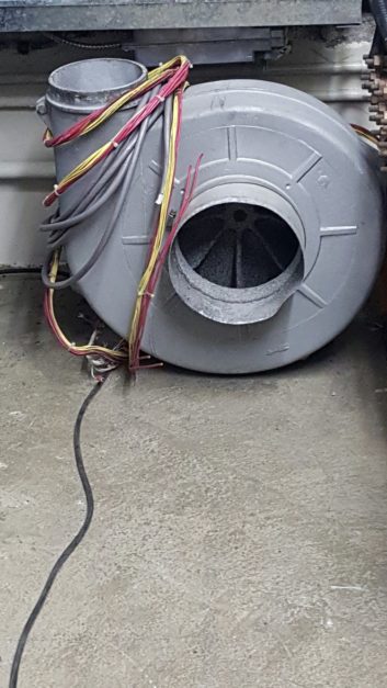
If you’ve never lost a blower motor in a high-power transmitter, your time probably is coming!
It is a helpless feeling when the transmitter completely shutx down. Then add the frustration of trying to find a replacement, not to mention removing the old motor and assembly.
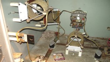
Honolulu contract engineer Dale Machado found a replacement blower and motor assembly to keep on hand, and added to the insurance policy by pre-wiring it. Adding the wiring harness is one less thing to think about when you are off the air.
In the case of three-phase motors, pre-wiring also reduces the chance you’ll miswire the phase, causing the motor to run backwards!
Data points
Consulting Engineer and frequent Workbench contributor Frank Hertel of Newman-Kees RF Measurement and Engineering compiled useful information for engineers working with AM stations. Frank bases the information on his own experience and on documents available from Kintronic Laboratories (www.kintronic.com).
Frank has been called in after lightning hits to repair a number of antenna tuning units at the base of AM towers. Lightning knows no season! Frank’s summary keeps things simple and easy to understand.
First discussed are estimated impedances for a single reference tower that is series-fed, and operating at 1000 kHz (1 MHz) at heights of 150, 90 and 60 electrical degrees. Under these conditions, the values in the first table are typical:
(150 deg. height) 782R –j13 (Capacitive Reactance
(90 deg. Height) 44R +j18 (Inductive Reactance)
(60 deg. Height) 11R –j113 (Capacitive Reactance)
If you are using an isocoupler on your (single) series-fed tower, it is assumed that the isocoupler has a typical capacitance of around 100 pF (or more). Thus, the isocoupler will present its added shunt value, to your single series-fed tower.
When the isocoupler’s shunt value is added in parallel to the impedance of your single series-fed tower, the addition of the isocoupler will shift the single tower’s impedance and typically yield the approximate values in the second table:
(150 deg. Height) 623R –j315 (Capacitive Reactance)
(90 deg. Height) 45R +j17 (Inductive Reactance)
(60 deg. Height) 10R –j105 (Capacitive Reactance)
Frank adds that a single 90 degree height, series-fed tower will normally use a simpler ATU matching circuit. This circuit may be more efficient as a result of needing fewer components and lessened power loss, but this is debatable.
A single series-fed tower that is shorter than 90 degrees will yield a low R value with capacitive reactance. A single series-fed tower that is taller than 90 degrees will yield a higher R value with capacitive reactance.
Finally, it is worth noting that a tower height of slightly more than 90 degrees should yield an R value of approximately 50 ohms with a manageable reactance value.
Spring is in full swing for many readers. If you find yourself doing AM work and needing AM components, visit the Kintronic site.
Unbalanced-to-balanced adaptor
Continuing discussions after the recent article about building an adaptor by Buc Fitch:
San Francisco contract and project engineer Bill Ruck also has built a number of unbalanced-to-balanced adaptors over the years. He is careful to pay attention to absolute phase — if you’re not, the design can invert the audio.
There is an easy fix to this; the input inverting op amp output is connected to Pin 3. The inverted unity gain IC connection is Pin 2. Swapping Pins 2 and 3 will ensure that the output is in absolute phase with the input signal.
Bill agrees with Buc as he also prefers to use +/–15 VDC as a power source, but he has also used inexpensive DC-to-DC converters to take a nominal 9 to 12VDC signal and make +/-15VDC.
And Bill has found it wise to add a small capacitor across the op amp feedback resistor in order to limit bandwidth and make the amplifier stable. Although this is not critical, he tries to pick a capacitor value to be equal to the resistance at around 150 kHz.
Storage strap
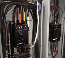
Over the years, we’ve shown a variety of cable management solutions from brands like Velcro and other hook-and-loop manufacturers. But the one in Fig. 2 serves a dual purpose.
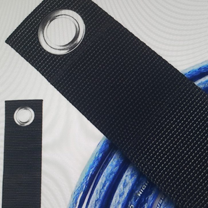
The metal grommet helps organize and hang bundles of remote broadcast cables. In the Technical Operations Center, the grommet secures large bundles of cables, especially of the Ethernet variety. The fastener secures the cables without deforming the wire wrap. This heavy-duty nylon strap is available from Koppy and they come in small, medium and large sizes. There is a quantity discount. Go to https://koppy.co/ .
John Bisset, CPBE, has spent over 50 years in broadcasting and is in his 31st year of Workbench. He handles western U.S. radio sales for the Telos Alliance. He is a past recipient of the SBE’s Educator of the Year Award.
Workbench submissions are encouraged and qualify for SBE recertification. Email [email protected].