It has always seemed a little odd to me that residents and governmental types are staunchly opposed to a single tower, a couple at most, that will enhance their communications. Yet, these very same people love acres and acres of windmills that scar the landscape for miles.

To be sure, this inconsistency can probably be chalked up to an exchange of compensation, not to mention the exercise of vogue politics. Despite this fact, the potential for opportunities for co-location of facilities can still abound, even with a hot AM tower.
No doubt, you just cringed at the thought of adding something to your stick or array, especially if your system is fractious and cantankerous. Those on the flip side will insist that a hot tower cannot be used under any circumstances.
As is usually the case, the truth is found betwixt the extremes, and so this month we look at the use of AM towers for other stuff.
The addition of this “other stuff” to an AM tower will affect the tower, or the stuff, to varying degrees, depending on the isolation scheme being utilized. Therefore, some schemes will work better than others will with certain topologies and AM antenna conditions.
ISCOCOUPLERS IN ACTION
Perhaps the most common way to add an antenna and transmission line to a base insulated AM tower is through the use of an isocoupler. Conceptually, this device couples the transmission line conductors at the significantly higher operating frequency of the system added to the tower, but keeps them decoupled at the AM operating frequency. This typically is accomplished by providing a high shunt impedance at the AM frequency, which in the case of a single isocoupler, tends to impact the tower impedance minimally.
As an example, consider a single tower antenna for 1000 at the heights of 150, 90 and 60 degrees. One of the popular modeling programs yields impedance values of 782-j13, 44+j18 and 11-j113 ohms, respectively, for these three towers. Assuming the isocoupler has a capacitance of about 100 pF, the resulting shunt impedance at 1000 kHz is 1600 ohms. This impedance is added in parallel to the impedance of the tower, and therefore the addition of a single isocoupler would shift the impedance to 623-j315, 45+j17 and 10-j105, respectively, for the three heights.
Note that the taller tower has a greater shift, which is the result of the parallel combination of two high impedances. Thus, an isocoupler may not be the best choice for a tall tower.
But, what happens if our tower is intended to be utilized for a wireless phone company desiring the installation of say 12 antennas and lines? Since an isocoupler would be necessary for each line, we are now looking at the parallel combination of the tower impedance and 12 isocouplers. Now our resulting tower impedances change to 21-j129, 51+j1 and 3-j6 ohms.
Obviously, a complete redesign of the ATU for the taller tower is necessary, while the quarter wave tower moves only a few ohms and could probably be handled by the existing ATU, if enough range is available. Most disturbing, however, is the short tower, which winds up with an impedance pretty darn close to a short at 1000 kHz. This impedance is close enough to zero that such a solution will probably not work. Unfortunately, some engineers have discovered this problem only after the installation was completed or well underway.
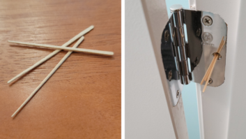
SKIRT THE PROBLEM
One solution to this problem is to ground out the tower by crossing the base insulator and installing a skirt or folded unipole.

With the tower itself now at ground potential at ground level, the transmission lines for the added stuff can be bonded directly to the tower itself. The skirt, of course, is connected back into the tower at some elevation, the height of which will vary the impedance at the AM frequency.
If changing over to this type of feed from a series feed, it is important to note that the impedance of the antenna at the AM frequency will likely have a much larger reactive component. As a result, a physical change in the components in the ATU will likely be required.
The use of isolation coils also provides a way to cross the base insulator. In this scheme, coax is wound into a cylindrical shape. This design also provides a high impedance across the insulator, but control over the impedance can be accomplished through parallel resonance with a variable capacitor, or by the inclusion of taps.
Use of these coils will necessarily increase the length of the transmission line utilized for the system installed on the tower, so insertion loss may become a concern. Additionally, depending on the requirements, some of these coils can be large, thus extra real estate is likely required for their cabinets and associated hardware.
One of the earliest methods of crossing the base insulator was for the transmission line itself to be placed on insulators standing it off from the tower. At the quarter-wave point, the transmission line would be bonded over to the tower itself, with this bonding continuing at regular intervals up to the antenna itself. This scenario functions as a quarter-wave stub, by transforming the short at the bond point to an open at the base, and thereby providing a high impedance at the tower base.
Short towers sometimes do not work well with this method, as the height is insufficient to produce the necessary high impedance across the base. The addition of a resonating capacitor between the outer conductor and the tower can alleviate this situation by adjusting for a high impedance. The insulators and capacitor, if so used, over time can, however, become a maintenance problem.
One solution that has been gaining traction is to use fiber optic cable to cross the base insulator. Under such a scheme, transceivers are placed both at tower and ground potential with the non-conducting glass used for the bridge. Accommodations still have to be made for equipment power on the tower side, although with lighting chokes or Austin transformers, it is easily accomplished.
BUT FIRST, DO THIS
Of course, before anything is added to an AM tower, a structural analysis should be performed.
In many cases, AM towers were engineered to be essentially naked. As a result, many times there is no opportunity under current standards to add things to a tower and still comply with loading limits.
Sometimes, analysis under the standard in effect at the time the tower was constructed is possible; however, if the additions would result in a greater than five-percent change in the loading, compliance with the current revision will be required. This may preclude cost-effective use of the site.
Finally, it is also important to remember that the addition of items to elements in a directional array bring in their own set of complexities. The addition of antennas and line will require a partial proof or remodeling, if applicable. These additions will also affect the self impedance of the tower, which will be different from the drive point impedance. Thus, any adjustments or apparatus used needs to take into account these differences, as well as differences that may occur between different patterns in the same array.
Using an AM site for additional communication services can be a very attractive option. Many times, AM antennas are located in areas where it is difficult or impossible to erect other new structures. Additionally, the presence of a developed site can be cost-effective for carriers and others seeking co-location.
Co-location also tends to quell the vociferous beefs of the NIMBY (Not In My Backyard) and BANANA (Build Absolutely Nothing Anywhere Near Anything) crowds, which is always good.
For the broadcaster, the benefit is a newfound revenue stream, which if engineered properly, results in minimal headache or problems for the existing AM operation.