In tune with detuning
Sep 1, 2005 12:00 PM, By Joe L. Bellis, CPBE
As the cellular and wireless business has matured, the tower construction fervor has subsided. Where construction of an average of one to two hundred towers per month was common for several years, new construction of only a few towers per year is now typical for most cellular operators. Additionally, many of the start-up cellular companies have been consolidated into a few major carriers. The current construction phase consists of repairs or modifications to the existing sites and construction of fill-in sites.

This is great news for AM broadcasters because that the constant barrage of new towers that affected a station’s coverage is over. Or is it?
As the existing cellular tower systems and sites age, the installed detuning systems lose their effectiveness. The cellular operators have engineers and technicians well versed in cellular systems but, in general, they have no concept of AM system operation. To the cell operator, there are no indications that the detuning system is no longer work properly.
I randomly selected inspections of 118 detuned sites around the United States that are owned or leased by various cellular licensees or tower owners. The inspections were completed within the past six years. The detuning systems were manufactured by several reputable companies that provide such equipment. The age of the installed detuning systems ranged from two years to 12 years.
In each case, the site was inspected as a result of modifications to the tower or as a result of another carrier being collocated on the tower, except in eight cases that were prompted by complaints from a radio station affected by the site.

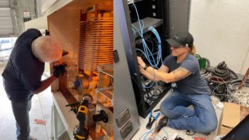
The fold wires and feed ring are shorted to this monopole tower. Typical for monopole towers, this occurred after the tower settled.
The statistics
Only 25 percent (30 sites) of the inspected sites were found to be in compliance and appropriately detuned. Seventy-five percent (88 sites) of the inspected systems were found to be defective due to mechanical modifications and problems of the tower site or the detuning systems were simply out of adjustment. Thirty-four percent (40 sites) had defective network components or were found to be using components that were beyond the tuning range needed for that system to be properly detuned. Three percent (four sites) were found to be improperly installed so that they had never functioned as a detuning system.
In almost all cases, the wireless licensees and or tower owners believed they were in compliance and properly detuned simply because the sites had a detuning apparatus.
Even more amazing, only eight (6.8 percent) sites were inspected because of radio station complaints. Yet, in about 50 percent of the inspected sites, the stations’ signals were seriously affected.
Governing FCC rules
The FCC Media Bureau and its predecessor branches have historically afforded considerable protections to the coverage patterns of standard broadcast licensees. The FCC created a detailed procedure for broadcasters to follow concerning interference and pattern distortions caused by additional licensed structures within 0.8km of a non-directional licensee or within 3.2km of a directional licensee in 73.1692 and frequently invoked that rule with construction permits. The rule requires impedance measurements of the affected antenna system and partial proof of performance antenna measurements as set forth in 73.154, and detailed antenna proof measurements for the non-directional antennas. The measurements are required to be filed with the FCC either prior to or simultaneously with the permittee’s application for station license.
Unfortunately for AM broadcasters, other bureaus of the FCC were not so concerned.
As cellular towers began to proliferate, the interference to broadcast antenna systems became apparent. AM broadcasters sought redress from the FCC. Following complaints, the FCC issued several opinions concerning sites and the related applications from specific complaints, but no particular rule governed all common carrier and wireless licensees. The wireless and cellular licensees continued to build towers for their systems without regard for interference to the AM broadcast systems. Finally, the FCC Common Carrier Branch (now the Wireless Telecommunications Bureau) codified the opinions into 22.371. This rule, or a form of it, has now been incorporated into virtually every branch of the FCC.

In addition to settling, regular tower wear, such as this broken stand-off insulator and loose safety cable, can affect the performance of a detuning system.
The rule states the Public Mobile Service licensee is responsible for �measures to correct disturbance of the AM station antenna pattern which [sic] causes operation outside of the radiation parameters specified by the FCC for the AM station, if the disturbance occurred as a result of the construction or modification.�
It states that if the construction or modification is located within 1km of a non-directional AM station or within 3km of a directional AM station, the station must be notified prior to the construction and modification.
It further states that �measurements must be made to determine whether the construction or modification affected the AM station antenna pattern� and that the Public Mobile Service licensee is responsible for the installation and continued maintenance of any detuning apparatus necessary to restore proper performance of the AM station array.
Much to the dismay of AM broadcasters, the rule does not specify definitive measurement procedures as in 73.1692. However, it requires measurements to prove the disturbance does not affect the station beyond the station’s control.
Of greater interest to the AM broadcaster, the rule does not specify grandfathering of existing sites prior to the rulemaking. Thus, all wireless sites are covered under the rule. The obvious exception is the case when the AM antenna system is constructed after the wireless site installation. Then the burden of detuning falls on the AM broadcaster.
FCC rule 73.1692 requires the broadcaster to show the antenna system operating within its licensed parameters regardless of the affect of the construction or modifications. It is concerned with operating parameter deviations and variances to licensed values prior to and following the construction/modifications and requires the licensee or permittee to correct the antenna system faults and variations accordingly, whether the faults or variations are caused by the construction and modifications or not.

The detuning network as found. In addition to the broken insulators, the coil is grounded at both ends.
The wireless rule, 22.371, is only concerned that the affect of the construction and modifications will not adversely affect the station’s coverage and operating parameters. It is not concerned that the station is operating at variance or deviation, except when the variance or deviation is caused by the construction and modifications.
Detuning in broadcasting
Historically in broadcast applications, detuning was simply the process of sectionalizing the reradiator into smaller segments that were inefficient radiators. This technique is readily seen in insulated guy wires. A guy wire has insulators at the tower attachment point and at the guy anchor point. Additional insulators are inserted along the guy wire at intervals of 0.10 wavelength or less of the station frequency so that the guy wires are inefficient radiators. Any remaining residual reradiation is considered inconsequential.
Series-fed towers in arrays typically float as an open circuit across the base insulator. In some cases, parallel resonant networks are used across the base insulator to enhance the isolation and further reduce residual current flow across the open circuit. This technique effectively sectionalizes the tower from the rest of the antenna system.
When a tower needs to be broken into smaller sections and insulators are too expensive or mechanically unstable, a cage assembly is used. The cage assembly consists of three or more fold wires that are equally spaced around the tower. The fold wires are attached to the tower at the top of the cage assembly and run parallel to the tower with appropriate insulators. They are then joined together at the desired point of sectionalization, remaining insulated, to form an open circuit. The fold wires are nominally set to be 0.15 to 0.20 wavelength long. The fold wires may be made that length physically or electrically, by the use of shorting stubs to the tower at the desired length.

A new detuning network. This one was built by LBA.
A network that provides a variable capacitance is attached between the open end of the cage assembly and the tower. It is adjusted to electrically lengthen the fold wires to an exact quarter-wavelength, creating a high impedance point at the open end. Generally, a sample loop is placed near the impedance point on the tower to adjust the variable capacitor and verify that the current is minimized. The cage assembly and the tower form a transmission line.
In some cases, sectionalization is used on towers that are too tall to be an efficient radiator at the AM frequency. The objective is to sectionalize the tower so that the main excited portion of the tower becomes an efficient radiator. Cage assemblies are generally employed for this purpose. Often the consultant will place another engineer at a particular distance, usually one mile from the antenna, with a field strength meter and a two-way radio. The consultant then computes the anticipated field strength at the distant point taking into consideration the various site constraints. The cage assembly network capacitor is then adjusted until the measured field intensity is reported to be as close to the calculated value as possible.
Water and power too
Electrical transmission lines and water towers are often a source of distortions to the antenna pattern, but transmission lines are usually only a problem when located close to the antenna system.
The electrical transmission lines themselves are far too long to be efficient reradiators. The primary reradiation effect is caused by a loop antenna effect. A loop antenna is formed from the base of one support tower to its top, across to the next tower through the sky-wire (overhead ground wire) and down the second tower. An earth return between the two towers completes the loop. Multiple adjacent loops are formed between the support towers. Although the formed loop antennas are non-resonant, considerable reradiation occurs because of the high excitation field from the broadcast antenna system, allowing the reradiation currents to circulate within the formed loop.
The steel towers are sectionalized in the same manner as in the broadcast antenna system except that generally a singular fold wire and network is used for each tower leg. A sample loop is placed just below each adjustment network and the network is then adjusted for a minimum current in each leg. As the tower legs are sectionalized, the induced RF signal floats to the same potential as that RF level in the overhead lines and the reradiation currents within the loop are eliminated.
Water towers are a different matter and may create reradiation problems even at some distance from the antenna system. Water towers typically use an iron pipe distribution system, buried just beneath the Earth’s surface, that forms a good RF ground system. As the height of the water tower approaches a quarter-wavelength, it becomes an efficient reradiator. Sectionalization at the base of the supporting legs divides the induced-signal circulating currents thereby reducing the reradiation. The detuning system configuration is much the same as with the power line towers.
Although the techniques described might lead you to conclude that detuned structures sectionalized towers, detuned water towers, other detuned structures, and detuned overhead power transmissions lines and towers are fairly common throughout the United States, quite the opposite is true.
Despite the simplicity of the concept of installing and maintaining a detuning system, the number of stations that use such systems is less than a few percent of the more than 4,750 AM stations. Quite often, where such systems have been used they have deteriorated or have been removed simply because of lack of station maintenance.

This radio station has a row of nearby detuned wireless towers. With regular maintenance to the detuning networks, this directional array remains stable.
Parasitic phenomenon
To understand the subtle differences between detuning a distant parasitic structure and a structure located within the AM antenna system, a brief review of parasitic reradiation is in order.
Antenna elements used in AM antenna systems are fed with transmission lines, but an antenna element can also be fed by the electromagnetic field of another antenna element. The most familiar example of this is used in beam antennas like those used at RPU frequencies.
The phenomenon can be visualized using a floating, one-half wavelength vertical wire in the field of a broadcast antenna. In as much as the wire is parallel to the electric component of the field, it will tend to short the electric field and current will flow in the wire just as if it were connected to a source of energy through a transmission line. The current will be at the same frequency as the incident field and will set up an electromagnetic field of its own. The resulting field will depend on the magnitude and phase of the field from the wire and the magnitude and phase of the current induced into the wire. The vectors add.
The effect of the incident field on the wire will be the same as if there were a series of small generators distributed throughout the entire length of the wire. The current distribution won’t be nearly sinusoidal as with one current source, but it will be the familiar bell-shaped curve, although somewhat distorted. The current will be zero at the ends of the wire and at maximum in the center. Conversely, the voltage will be at maximum at the ends. The same phenomenon occurs with a wire one-quarter wavelength long that is grounded.
Grounded, one-quarter wavelength structures and ungrounded one-half wavelength structures have the greatest potential as reradiators. Fortunately, few structures of one-half wavelength or taller are ungrounded. Generally, the majority of the reradiators that require detuning will be grounded structures that have heights that fall between one-eighth wavelength and one-half wavelength tall.
Distant detuning
With sectionalization, the objective is to impede or stop the current flow along a single conductor that is generally fed from one source at a point along the structure. Sectionalization effectively creates an open circuit to that current flow along the structure.
In detuning, the objective is to cancel the resultant field of the induced current within a particular structure. To develop the equal and opposing fields within the structure and detuning section the current must be maintained. This is readily accomplished because the structure is excited along its entire length, as if there were a series of generators or signal sources at every point along the structure.

This two-tower array measured considerable variations in its field reading tests.
The cage assembly is used in a similar manner as in the sectionalization process with the cage assembly wires forming parallel conductors to the structure. The detuning section forms a closed-loop circuit.
The current is induced into the structure, flows across the cage assembly attachment point and down the cage assembly to a network returning to the structure. The network adjusts the current to a point that the field of the cage assembly is equal in magnitude to the field of the structure thereby canceling the fields. The fields are about 180 degrees out of phase with each other because of the mechanical configuration of the structure to the cage assembly being equally spaced and parallel to the structure.
The similarity between the sectionalization process and the detuning process make them appear identical, but they are not. The subtle difference is more apparent when viewed out-of-the-box.
Sectionalization is effective when used over a low-loss ground system with systems generally fed from a single current source. The sectionalization presents a high impedance point to the unwanted signal. The detuning process has no effective ground return (only lossey earth), is fed along its entire length and must maintain the induced current to cancel the resultant fields.
As the detuning system is adjusted to the point of sectionalization, the earth losses are removed. The incident source signal excites the structure and the cage wires in phase because the source is much greater than the opposing fields. The resultant reradiated field increases. As the system is further adjusted, the magnitude of the opposing field in the cage wires approaches the magnitude of the field of the structure and the resultant reradiated field is cancelled.
Measuring detuning system effectiveness
An antenna partial proof does not prove the effectiveness of a detuning system. The antenna partial proof only proves the instant antenna pattern compared to the last known pattern analysis, either by full proof or partial proof, and is dependent on the instant operating parameters of the station and other environments beyond the control of the station.
If the reradiating structure is constructed in the immediate near field of the antenna system, the operating parameters will change because of the mutual coupling between the structure and the elements of the antenna system. As the reradiating structure is appropriately detuned, the mutual coupling will be eliminated and the operating parameters will return to their pre-construction values. Adjustments to the array, due to the influence of the reradiating structure, generally are not required. Sectionalization in this case is not appropriate detuning. The residual reradiation level of the sectionalized structure will require some adjustment to the array, which changes the operating parameters.
If the reradiating structure is beyond the immediate near field of the station and if a proof radial lies through or nearly through the reradiating structure site, the radial measurements may or may not reflect the localized influence of the reradiator. This ambiguity occurs because the reradiated signal is vectorally added to the ambient signal.
While similar to partial-proof measurements, proof-type measurements made immediately prior to and immediately following the construction and detuning of a structure serve only to indicate the distortion or deviation effect, if any, caused by the reradiation level of the detuned structure. These measurements provide a baseline and a comparison for pre- and post-analysis and do not reflect the actual station pattern condition. Any similarity of these measurements to the actual partial proof measurements of the station for pattern analysis is purely coincidental.
Near-field measurements
Appropriately made near-field measurements at the base of the reradiating structure accurately gauge the reradiation from the structure relative to the ambient field intensity of the station being protected.
The measurement points required to implement this approach are laid out along a line beginning at the center of the structure and proceeding outward at a bearing of 90� from the structure to the center array coordinates of the radio station. This quadrature radial generally extends outward to a distance of 200′ to 300′ from the center of the structure. Marks are made at regular intervals beginning as close to the structure as possible and offset corrections are made to ensure that each point is at a 90� vector between the structure and the station. The field intensity meter is placed over each point. The meter is aligned directly on the structure and a reading of the reradiated signal is taken. The meter is turned 90� and a reading of the incident field from the station is taken. Measurements are made at each point along the quadrature radial in the non-detuned mode and the detuned mode. The data is corrected for near-field effects, tabulated and graphed. Thus, the structure reradiation and the detuned reradiation are accurately determined. The detuned reradiation level is directly compared to the minimum signal level of the array to determine the affect to the station. The effectiveness of the detuning system is the calculated difference between the structure reradiation level and the detuned reradiation level expressed in decibels.
A monitor point along the quadrature radial will serve as a valid means to determine the operational condition of the detuning system in the same manner that a monitor point for the station array.
Joe Bellis, PhD, was the owner/president of RMF Associates, Cape Girardeau, MO, when he prepared this article. He died July 29, 2005. He was a member of the SBE, the IEEE and NARTE. In his career, Bellis authored many articles and papers on RF transmission, radio and electronic colling systems and radio propagation and communications in desert environments.